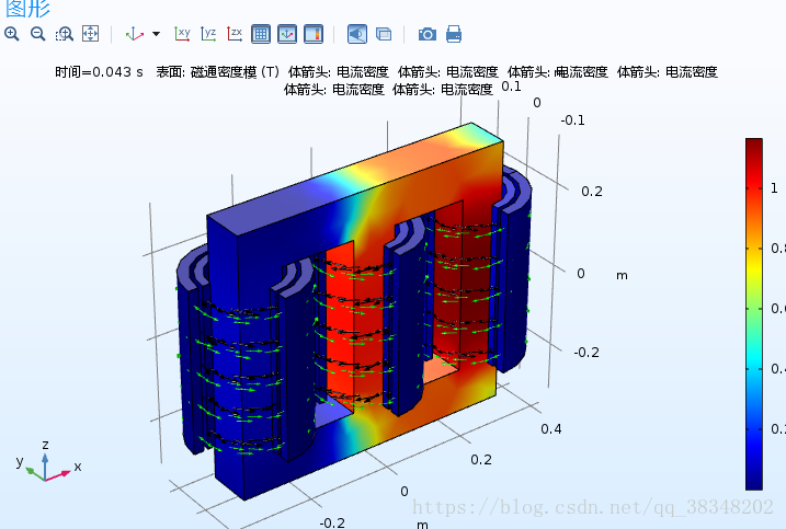
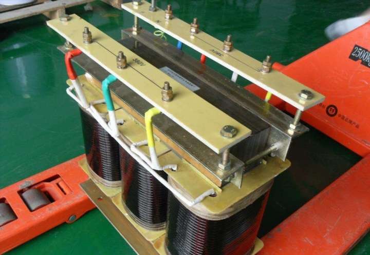
Lets know more on construction of a three phase transformer
| 1.what is a 3 phase transformer? |
| 2.how 3-phase transformers are constructed? |
| 3.can a 3 phase transformer be used for single phase? |
1.what is a 3 phase transformer?
Three-phase, as the name implies, refers to the connection of three single-phase circuits relative to single-phase. For transformers it is the inner and core structure, each core forms a separate loop, and there is no relationship between each single-phase loop. Because each has the same core, their no-load current is exactly the same.
Here we introduce a specific three-phase transformer example 40MVA 34.5KV-4.16KV-4.16KV, Three-Phase, 60-Hertz, Power Transformers, and then comprehensively understand the construction of three phase transformer from various parameters.
The cost of a three-phase transformer needs to be considered:
1)
ii) Neutral Grounding Resistor
iii) Costs for off-loading of the transformers and NGRs at delivery point as an option
iv) Costs for transportation from temporary lay-down yard to formal transformer pads,
Installation & testing at Owner’s plant site as option as an option
Note1) The options iii) & iv) shall NOT be included in total price.
You may enjoy: Pad Mounted Transformer
Complete description of construction with approximate dimensions and weights
3) Outline drawings including air terminal chamber's details and air terminal lugs Sheet 2/10
4) Details for design of foundation
5) Catalogues and technical data including % impedance, no load loss & total losses
Total losses shall be the self-cooled or base rating.
6) Drawing schedule
7) Delivery schedule of transformers
8) Installation & test schedule
9) Plus any additional information requested in attached “Specification for Substation
Transformers”
10) Specification sheet transformer fluid
11) Specification sheet or catalog for Sudden Pressure Relay (Rapid pressure rise relay) and Automatic Resetting Tank Pressure Relief Device with Alarm Contacts (63P)
Installation/Testing work for the four (4) transformers at Owner’s plant site shall comprise the
followings;
1.3.1 Off-loading
1) Receiving inspection of the transformers & radiators prior to the off-loading by factory
authorized specialist to maintain the manufacturer warranty of the transformers.
This includes analyzing the impact recorder tapes and if necessary internal inspection of
the transformers.
Off-loading the transformers and NGRs at temporary lay-down yard in Owner’s plant site.

The transportation of three-phase transformers needs to be taken into account:
1.3.2 Transportation & Installation
1) Lifting and transportation of the transformers and NGRs from temporary lay-down yard to
formal transformer pads.
2)
Installation of radiators, cooling fans & grounding resistors.
3)
Connection of transformers to grounding grid.
4)
Oil filing of the transformers in accordance with the manufacturer guidelines.
5)
Installation of Inertaire oil preservation system
Three-phase transformer testing needs to be considered:
Power factor (Doble) test of windings
2) Megger test of windings
3) Verification of core grounding
4) Turn ratio test of all taps
5) Impulse Testing
6) Sound Testing
7) Temperature Rise Testing
8) Current transformers; megger, ratio, saturation & polarity test
9) Calibration and operation of winding, oil temperature thermometers & oil level indicator
10) Function tests of Functional tests of pressure relief device, rapid pressure raise relay, forced
cooling system & Nitrogen purge system
11) Megger test and resistance test for neutral grounding system.
Note: The owner or owner’s representative reserves the right to witness all field tests. The three phases transformer
shall notify the owner 72 Hrs. in advance of any tests.
2.how 3-phase transformers are constructed ?
Then we are looking at the various parameters of the construction of three phase transformer in detail:
The transformer shall be manufactured and shipped in accordance with following specification and
attached engineering specification
2.1 The transformer shall be oil filled. The oil shall be FM approved “NON (Less) flammable fluid”,
such as EnvirotempTM FR3 or equivalent.
2.2 Primary winding shall be 34,500-volts.
2.3 The transformer primary shall be Delta connected.
2.4 The three phases transformer shall provide high-voltage air terminal chamber on side of transformer arranged for
2-1C-500MCM cu. /phase (40MVA, 34.5-4.16KV-4.16kV) and 1-1C-500MCM cu. /phase (20MVA, 34.5-4.16KV), 35KV cables compression lug connection, entering from bottom of the chamber using 24” cable tray [See attachment-1] and 1-1C-500MCM cu. /phase (20MVA, 34.5- 4.16KV), 35KV cables compression lug connection, entering from front of the chamber using 24”
cable tray
2.5 High voltage terminal chamber shall have sufficient space from cable tray entry point to compression lug connection to allow for fanning incoming cables and installation of stress cone
terminations.
Cable supports made by fiber glass in the chamber shall be furnished by the three phases transformer.
2.6 The transformer primary winding full rated KVA taps shall be two 2-1/2 percent above and below rated voltage. Taps shall be accessible by externally operated changer with provisions for locking with a padlock and will not be changed under load. Provide a 1000/5A ratio for 40MVA and a 600/5A ratio for 20MVA, bushing type, current transformer on each primary bushing for Owner's transformer differential relaying.
Accuracy : C200 or greater
Polarity : Subtracting --- Polarity mark shall be labeled on the CT
2.7 Both of Secondary and Tertiary of 40MVA shall be for 4,160 volt operation wye-connected and Secondary of 20MVA shall be for 4,160 volt operation wye-connected. The neutral shall be isolated and extended to outside for external connection of neutral resistor. Provide a 50/5A ratio
(C100 Accuracy), window type, current transformer on the neutral bushing for Owner’s ground fault relaying.
2.8 Both Secondary and Tertiary for 40MVA shall have low voltage air terminal chamber on side of Sheet 5/10
transformer arranged for 3,000 Amp bus connections and 20MVA shall also have low voltage air
terminal chamber on side of transformer arranged for 3,000 Amp bus connection.
2.9 The transformer painting shall be special epoxy paint treatment against corrosion.
2.10 The transformer impedance shall be as follows
40MVA Transformer
34.5KV- 4.16KV , 7.8%, w/-0.0% tolerance, +7.5% at 40MVA
34.5KV- 4.16KV , 7.8%, w/-0.0% tolerance, +7.5% at 40MVA
4.16KV- 4.16KV , 15.6%, w/-0.0% tolerance, +7.5% at 40MVA
20MVA Transformer
7.0%, - 0.0% tolerance, + 7.5% at 20MVA
2.11 The transformer primary shall be suitable for over excitation (10 % above any tap value) with rated
output KVA, and without exceeding 55℃ temperature rise.
2.12
The transformer shall be provided with a sealed tank preservation system and a positive pressure
Nitrogen gas system with cylinder.
2.13
The transformer bushings and spades [See Attachment-3, sample drawing]
1) High Voltage bushings and spade – 34.5KV, Mounted in air filled terminal chamber,
200KV BIL mounted on side. 2) Low Voltage bushings and spade - 5KV, complete with flange for metal enclosed
3,000A bus duct connection, 75KV BIL, mounted on side
3) Neutral bushings and spades- Cover mounted 5KV, metal enclosed
2.14 Provide the following NEMA-ANSI accessories on transformer.
1) Bottom Drain and Filter Press Valve with provision for Sampling
2) Jacking Bosses
3) Cover Lifting Eyes
4) Transformer Lifting Lugs
5) Liquid Level Gauge with Low-level Alarm Contacts (71Q)
6) Manhole in Cover
7) Pulling Eyes
8) Vacuum Pressure Gauge with a TCG sample valve/kit Sheet 6/10
9) Automatic Resetting Tank Pressure Relief Device with Alarm Contacts (63P)
10) Base Suitable for Skidding along either Centerline
11) Liquid Temperature Indicator with Alarm Contacts (26Q)
12) De-energized Tap Changer, Externally Operated with LOTO
13) Tank Grounding Pads
14) Sudden Pressure Relay (Rapid pressure rise relay) with Seal in, Reset Device & Test
Provisions at Transformer.
125V DC Operation
15) Hot Spot Indicator with Alarm Contact (49T)
16) Tank and Radiators Designed for Full Vacuum
17) Forced-air Cooling Equipment
18) Current Transformers on Primary Bushings specified Para 2.6 on this specification above.
19) Neutral Grounding Resistors and Current Transformers
Note: Neutral Grounding Resistor shall be continuous rating.
20) Plus any additional information requested in attached “Specification for Substation
Transformers” [Sheet Nos. E80-720]
2.15 Control Voltage
Control power for transformer is as follows:
Fans 115V, 1PH, 60Hz
Sudden Pressure Relay 125V DC
The three phases transformer shall furnish with his quotation the approximate KVA required for fans.
2.16 Terminal Box and Wiring
Terminal box with all alarm and trip contacts wired to terminals. Wiring shall be run in galvanized steel conduit. External conduit with interconnecting wires shall enter the bottom.

3.can a 3 phase transformer be used for single phase?
Of course, three-phase transformers can be used as single-phase to operate.
Here is a method introduction:
For example, for a three-phase transformer connected by WYE/WYE, if the three windings on the high and low voltage sides are connected in parallel with each other to form a single winding, it can be used as a single-phase transformer. In another case, if the three windings are not connected in parallel, we can consider using only one set of windings corresponding to the high and low voltage sides, and all the remaining windings are used for grounding, but the transformer capacity at this time will only be 1/3 of the original. At the same time, his attrition rate will also increase.
WELCOME TO CLICK HERE AND INQUIRY MORE ABOUT 150KVA TRANSFORMER DETAILS.

