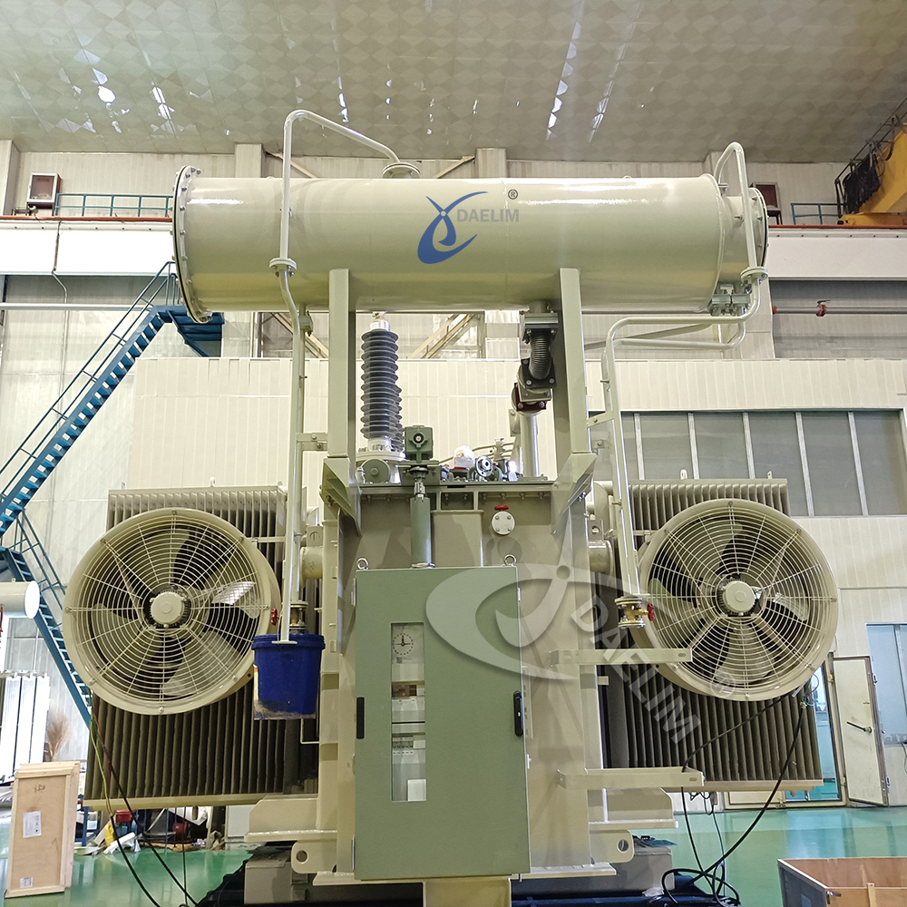
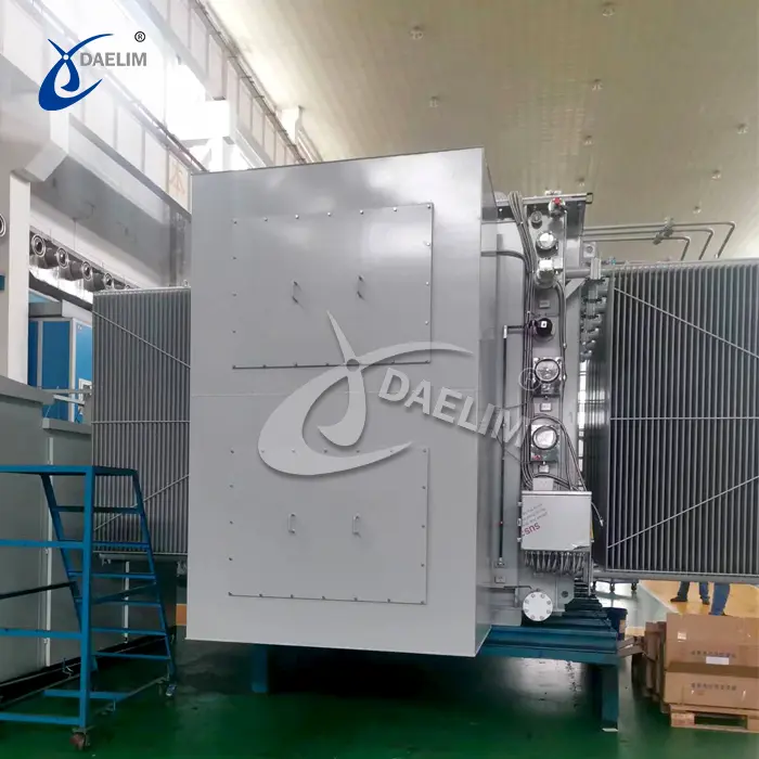
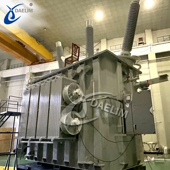
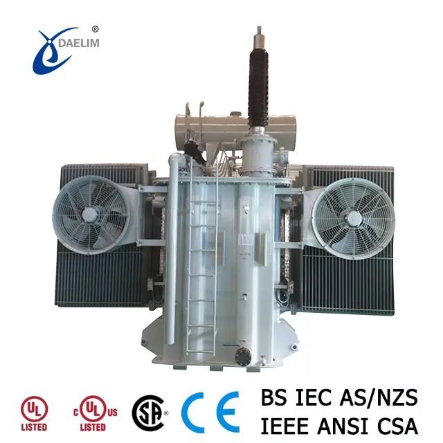
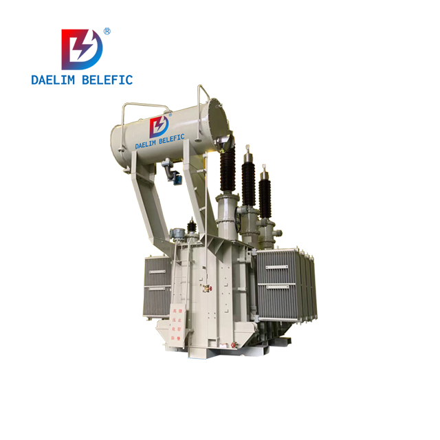
16.2 / 21.6 / 27 MVA Generator Step-Up Transformer

- Primary Voltage Ratings: 46kV/34.5kV
- Secondary Voltage Ratings: 13.8kV
- TYPE: Oil-Filled, Outdoor, Station Type, Power Transformer
- BIL: 250/200kV
- Standards: IEEE
- Application: Renewables
- Power Rating: 16.2MVA / 21.6MVA / 27 MVA
- Cooling Method: ONAN/ONAF1/ONAF2
Daelim Transformer is proud to offer advanced 16.2 / 21.6 / 27 MVA Generator Step-Up Transformers designed for optimal performance and efficiency. Our transformers feature high-quality copper windings, a robust silicon steel core, and versatile cooling systems. With ratings up to 27 MVA and compliance with ANSI, IEEE, and NEMA standards, they ensure reliable operation and adaptability. Daelim Transformer delivers cutting-edge solutions to meet the evolving needs of the energy sector, driving sustainability and excellence.
Quote Now
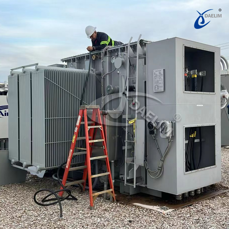
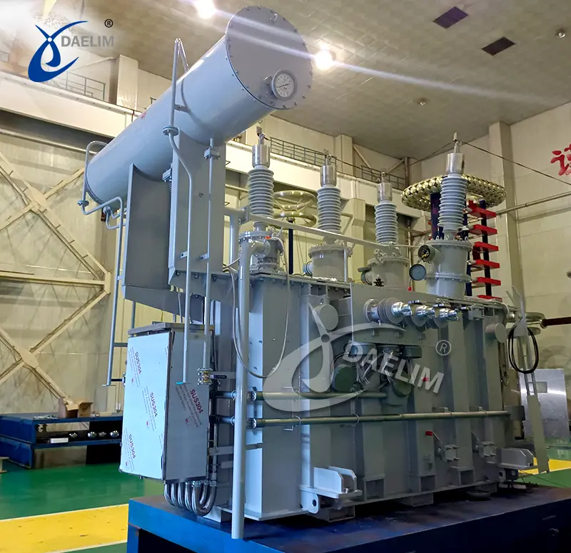
In September 2024, Daelim Transformer proudly supplied two state-of-the-art 16.2 MVA / 21.6 MVA / 27 MVA Generator Step-Up Transformers to a leading renewable energy client in the United States. Our commitment to quality and innovation ensures that every transformer we deliver meets the highest standards of performance and reliability.
Daelim Transformer is dedicated to providing cutting-edge solutions that enhance energy efficiency and sustainability. With decades of experience and a reputation for excellence, we offer transformers designed to meet the evolving demands of the energy sector.
All transformers, components (including, but not limited to, all threaded fasteners), and materials conform to the applicable standards of ANSI, ASME, ASTM, IEEE, and NEMA. They meet all industry and safety standards and are designed, fabricated, and tested according to ANSI/IEEE C57 Series, NEMA TR1, and these specifications.
The Generator Step-Up Transformers feature a three-winding core type with the following voltage ratings:
- High Voltage (HV): 46 kV Grounded Wye
- Medium Voltage (MV): 34.5 kV Grounded Wye
- Low Voltage (LV): 13.8 kV Buried Delta
Cooling is provided in two stages:
- Self-Cooled (ONAN): 16.2 MVA
- First Stage Air-Cooled (ONAF1): 21.6 MVA
- Second Stage Air-Cooled (ONAF2): 27 MVA
Winding Material: Both HV and LV windings are made of high-quality copper.
DESIGN AND CONSTRUCTION
Each transformer is engineered to:
- Operate continuously at no load at 110 percent, or as specified, of any available tap-rated output voltage without exceeding the average temperature rise by resistance specified on the data sheets.
- Operate continuously at maximum rated load at 105 percent, or as specified, of any available tap-rated output voltage without exceeding the average temperature rise by resistance specified on the data sheets.
- Accommodate "Planned Loading Beyond Nameplate" in accordance with IEEE C57.91, up to 125 percent of the maximum rating of any winding.
VOLTAGE RATINGS
- HV Winding: 46 kV
- LV Winding: 34.5 kV
- Tertiary Winding: 13.8 kV
MVA RATINGS
- ONAN: 16.2 MVA
- ONAF1: 21.6 MVA
- ONAF2: 27 MVA
IMPEDANCE
The impedance between the high-voltage and low-voltage windings at the self-cooled rating is 8.5%.
CORE
The transformer core utilizes high-quality, non-aging silicon steel with superior permeability and low hysteresis losses. The core is grounded at a single point, and core grounding is brought out on the cover through a bushing and grounded externally to facilitate testing.
CORE GROUND
The core ground is brought out of the transformer tank through a 1.2 kV bushing and connected to the tank via a disconnectable link.
WINDINGS
All windings are crafted from copper to minimize eddy current losses and ensure optimal mechanical strength. All conductor joints are brazed or welded for maximum reliability.
ANGULAR DISPLACEMENT AND POLARITY
The angular displacement between the high-voltage and low-voltage winding vectors is 30°, with the low voltage X1 lagging the high voltage H1, H2, H3 rotation. The phasing and polarity of the transformer conform to ANSI Standard C57.12.70.
DE-ENERGIZED TAP CHANGER (DETC)
Each transformer is equipped with a de-energized tap changer on the HV winding featuring 5 positions:
- (2) 2.5% above rated voltage
- (2) 2.5% below rated voltage
The tap changer includes a tap position indicator and provisions for padlocking the operating mechanism in any tap position. The indicator is visible from the ground, and the handwheel or lever is easily operable from the ground.
TANK CONSTRUCTION
The transformer tank, all oil-filled compartments, and accessories are designed to withstand full vacuum. The cover is welded and includes lifting eyes, a mechanical pressure-relief device, two manholes for inspection, and mounting bushings.
PRESSURE RELIEF
The pressure relief device is self-resealing and requires no replaceable parts to restore it to working condition after activation. The device operates at a pressure lower than the maximum pressure the tank and cover are designed to withstand and includes a mechanical trip indicator and alarm contacts.
The transformer is equipped with lifting attachments for the removal of covers, radiators, or radiator banks.
TEMPERATURE RISE
The temperature rise by resistance may reach but not exceed 65°C. The hottest spot temperature rise will not exceed 80°C over an ambient temperature of 40°C, provided the average temperature of the cooling air for any 24-hour period does not exceed 30°C, ensuring the longevity of the transformer.
COOLING SYSTEM
The cooling system includes fans, pumps, drive motors, integral piping, and controls. The equipment features the following contacts suitable for operation on 125 VDC:
- Winding Temperature:
- Stage 1 cooling fan at 80°C
- Stage 2 cooling fan at 90°C
- Alarm point at 95°C
- Alarm point at 105°C
- Trip point at 110°C
- Top Oil Temperature:
- Alarm point at 90°C
- Trip point at 95°C
The cooling system controls include, but are not limited to, combination motor starters, relays, terminal blocks, CPT, and circuit breakers. Each fan is individually protected with a suitable thermal device. The cooling system control is designed to allow either group to operate preferentially as the first or second stage of cooling, with the option to reverse the order to equalize wear between the two groups.
FANS
Radiator-type coolers are equipped with fans designed to operate automatically from the winding temperature relay control and manually from an ON-OFF switch in parallel with automatic control.
FAN MOTORS
Fan motors are totally enclosed, weatherproof, and rated for continuous duty. They include overload protection, circuit protection, magnetic contactors, and a manual control switch mounted in a weatherproof cabinet. Integral horsepower motors have a NEMA Design B torque characteristic unless otherwise specified by the driven equipment.
Daelim Transformer—where innovation meets reliability. Trust us to deliver exceptional performance and efficiency, transforming your energy solutions for a sustainable future.
Related Products
Related Article
Canadian 69 kV Substation Transformer Project
Today, we are excited to present a case study on a 69 kV substation transformer project by Daelim Transformer. Our Canadian client required a step-down transformer for their substation to connect with the hydroelectric grid in Quebec.
230 kV Three Phase Power Transformer For USA Market
In 2023, Daelim Transformer designed and manufactured a cutting-edge 230 kV three-phase power transformer for a client in Nevada, USA. The client recently shared installation and operational photos, showcasing the successful deployment of this remarkable transformer. Let's delve into the specifics of this transformer project!
Pad Mounted Transformer for BESS System 4.0 MVA in Riverside County, California
Today, Daelim Transformer is proud to introduce a pad-mounted transformer for a 4.0 MVA Battery Energy Storage System (BESS) project located in Riverside County, California. The transformer is meticulously crafted to comply with the specifications outlined in the California Electrical Code Article 450.
13.8 kV 10.5 MVA Substation Transformer for Ecuador
A customer from Ecuador contacted Daelim Transformer for a 10.5MVA substation transformer (13.8kV high voltage, 2.4kV low voltage). Daelim Transformer provided a customized solution, conducted virtual factory tours, ensured rigorous quality control via video inspections, and offered post-delivery online training and ongoing support, fostering a successful partnership.
20MVA Power Transformer for the United States
This project involves the development of a 20 MVA three-phase power transformer tailored for the United States market. The primary voltage is 24.94kV, and the secondary voltage is 4.16kV, indicating it functions as a step-down transformer. The design and production fully comply with IEEE C57.12.00 standards and have passed third-party UL team testing. All accessories also adhere to IEEE standards. FR3 vegetable oil serves as the insulating liquid for the transformers.
Pad Mounted Transformer For High Voltage Substation
FWS commissioned Daelim Transformer to design and manufacture a new high voltage substation for the Richardson International Canola Crush facility expansion in Yorkton, SK. The project required two specially designed top-in pad-mounted transformers, one 2 MVA and one 5 MVA. Unable to meet the delivery deadline, local North American suppliers led FWS to choose Daelim Transformer for their capacity and quality. The transformers were successfully produced and delivered within 16 weeks and are now operating safely.


DOE
AS
GOST