
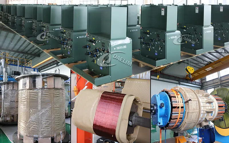
Transformers use different winding types to maximize efficiency, cooling, and performance for various applications.
In this article, you’ll discover types of transformer windings in core type and shell type transformers, including disc, helical, sandwich, and crossover windings.
We’ll break down each type’s unique structure, cooling benefits, and practical applications, so you can understand how different transformer winding can serve your needs.
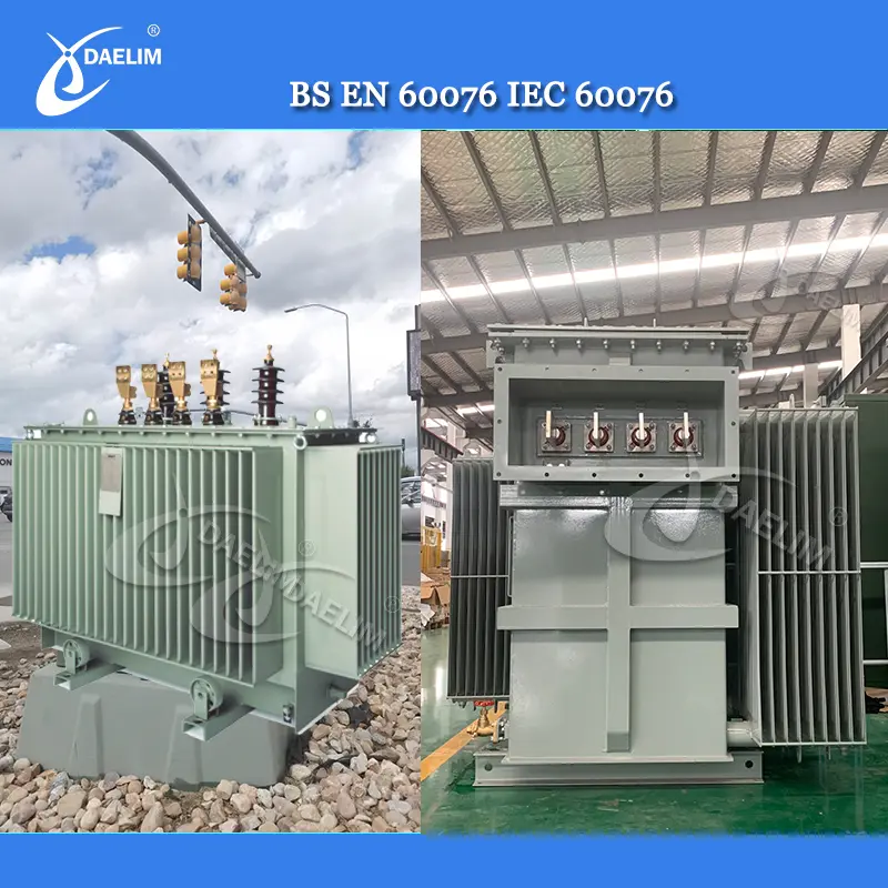
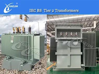
ECO design transformer(Tier 2) complies with the latest energy efficiency standards of the European Union, and has silicon steel core and amorphous alloy core transformers. Designed and produced according to IEC and BS standards, it is energy-saving, environmentally friendly and highly efficient.
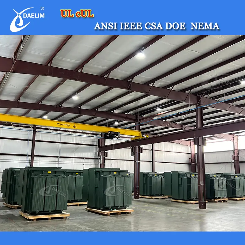
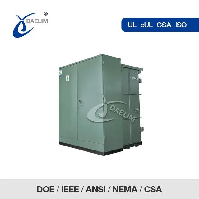
At our facility in Houston, we have hundreds of transformers in stock, including pad-mounted transformers ranging from 300 kVA to 3000 kVA, with voltage levels of 12.47, 13.2, 13.8, 24.94, and 34.5 kV. We also offer single-phase transformers with capacities from 50 to 175 kVA. There’s no need to wait—immediate shipment is available!
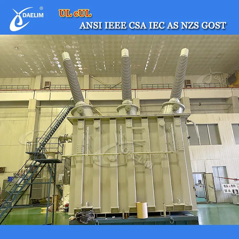
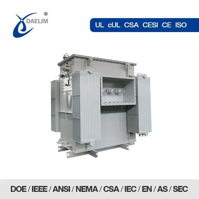
Daelim Transformer offers a complete line of oil-immersed transformers that meet current applicable standards, including IEC, IEEE, ANSI, CSA, NEMA, AS/NZS, and GOST. Our high-voltage power transformers are available for voltages up to 230 kV and ratings up to 300 MVA. We have successfully supplied hundreds of high-voltage power transformers across America.
What is Transformer Winding?
The transformer winding is the main working part of the transformer, and it consists of an insulated conductor material that is wound around the transformer core. This establishes a working mechanism that works to transfer the magnetic flux from one side to the other side of the core and transfer electrical energy between circuits.
The arrangement and design of the transformer winding directly influences the transformer efficiency, voltage regulation, cooling performance, and the short circuit strength.
In a transformer, the primary and the secondary transformer windings are designed according to the specifications provided by the client and according to the transformer voltage class, power rating, and application requirements. The different types of winding in transformer construction are selected according to the optimization needed, the current-carrying capacity, the insulation format, and according to the heat dissipation mechanism of the electrical transformer.
Common Types of Transformer Winding
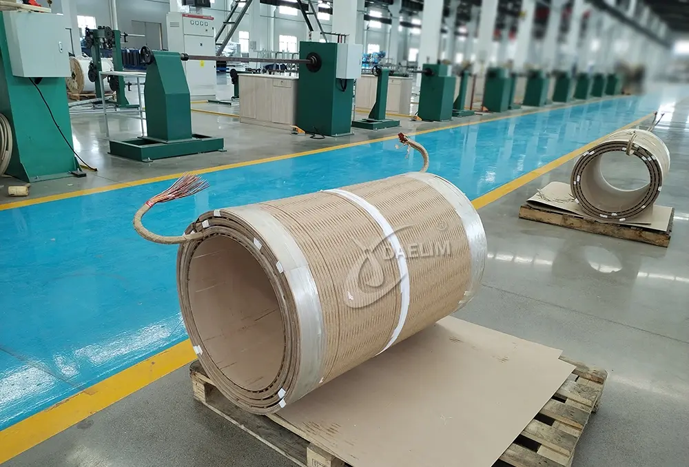 At DAELIM Transformer, we use different transformer windings for different functions and configurations.
Windings are arranged to produce a magnetomotive force (MMF), which the core transfers to other windings to achieve different voltage levels.
Broadly, transformers are classified into two main types based on their core structure and winding arrangement:
- Core type transformer
- Shell type transformer
In our core type transformer, you’ll see the winding wrapped around the core. In contrast, with a shell type transformer, the core itself encases the winding.
Our winding design considers factors like current rating, short-circuit capacity, temperature limits, impedance, surge voltage, and transport requirements.
How About Transformer Winding Type For a Core Type Transformer?
Helical Winding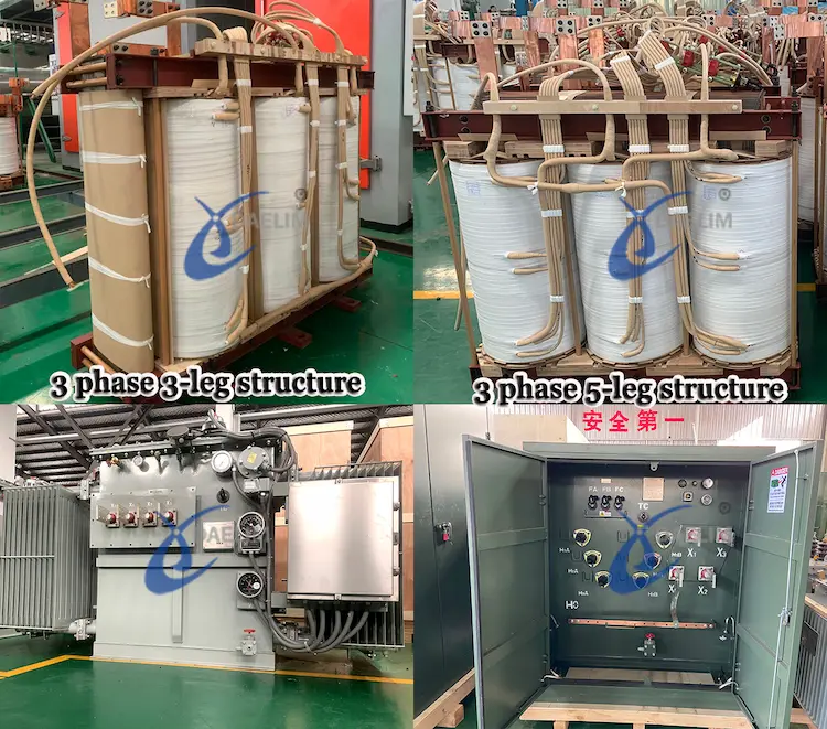
Helical winding comes in four forms, single, double, disc-helical, and multi-layer. We use helical winding in our low-voltage, high-capacity transformers.
It is made up of rectangular conductor strips wrapped in helix form, positioned radially in parallel layers.
Each turn spans the full radial depth of the winding. We use the utmost 16 parallel strips to make a conductor.
Generally, we use four types of helix winding in our power transformers:
- Single Helix Winding: We orient single helical windings in an axial direction, following an inclined, screw-like path. Each winding has a single layer of turns, offering a streamlined design suited for low-voltage applications.
- Double Helix Winding: Double helical winding minimizes eddy current loss by reducing the number of parallel conductors. The design enhances transformer efficiency and reduces overall energy loss.
- Disc Helical Winding: We arrange strips in parallel and side by side along the radial direction to fully cover the winding’s radial depth.
- Multi-layer Helical Winding: We utilize this type of winding in our high-voltage transformers with ratings of 110 kV and above. We use multiple cylindrical layers, concentrically wound and we connected them in series.
Advantages of Helical Winding in Transformer Design
The main reason why helical winding in transformers is so widely preferred, specifically for low-voltage and high-current windings, is because of the excellent mechanical strength and superior cooling characteristics of this winding type. The specific continuous helical arrangement of the conducting material allows the current to be distributed very evenly across the entire conducting material. This also helps to reduce the circulating losses of the transformer winding, also known as copper losses, and increases the overall efficiency of the transformer. Another main advantage of the helical winding used in electrical transformers is the availability of cooling ducts between the conductor layers due to the unique design of the helical winding. Oil circulation between the winding layers thus helps heat dissipation more efficiently. In applications that involve large power transformers, the helical winding in transformer construction also provides enhanced resistance against the mechanical stresses produced inside the transformer during each loading condition.
Cylindrical Winding
For our low-voltage transformer with a power rating of 600-700 kVA and a current of 10-600 A, we use cylindrical winding.
We apply cylindrical windings in their multi-layer form. Rectangular conductors are used in a two-layered type to secure the lead-out ends.
The layers of the windings are separated by oil ducts, allowing for effective cooling as oil circulates throughout the winding structure.
Continuous Disc & Disc Winding
We mainly apply disc winding in our power transformers as it facilitates a reliable transformer design. For the winding, we use discs or flat coils arranged in either series or parallel.
We create the coils from rectangular conductor strips, wound in a spiral pattern outward from the center in a radial direction.
One or more strip conductors are wound in parallel along the flat side, lending strength and durability to this winding style.
Each disc is spaced by sectors attached to vertical strips, while additional spacers create radial and axial ducts.
This design allows oil to circulate directly around each turn, facilitating efficient cooling and maintaining optimal transformer performance.
The advantage you get from disc and continuous disc winding is greater mechanical axial strength and affordability.
Why Disc Winding Is Used in Power Transformers
In the electrical transformer industry, disc winding in transformer construction is one of the most widely used arrangements for all types of medium and high voltage applications. In this specific design, the winding is initially divided into several small disc-shaped coils. All these are connected with each other in series. This allows voltage to be distributed more uniformly across the entire winding structure of the transformer.
The one major advantage of using this winding in transformer design is the presence of axial and radial cooling ducts in the design. These ducts help improve oil circulation within the transformer winding area and help improve the heat dissipation and cooling of the transformer in peak loading conditions. This helps maintain a lower operating temperature and increase the transformer’s lifetime.
Other than this, the windings provide excellent mechanical strength that makes them suitable for transformers that are subjected to frequent fault conditions.
Crossover Winding
On many occasions, we apply this type of winding in the high-voltage winding of our small transformers.
We separate the layers of winding 0.5 to 1 mm and ensure the voltage is maintained at 800 and 1000.
Normally, the crossover type of winding has more strength compared to the cylindrical type of winding. Also, don’t forget that crossover winding has lower impulse strength than cylindrical.
You will also incur more labor costs when using a transformer with a crossover type of winding.
Types of Transformer Winding For Shell Type Transformer
Sandwich Type Winding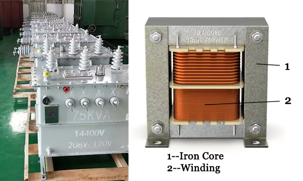
In sandwich windings, primary and secondary windings are arranged in alternating layers, basically “sandwiching” them together.
The design enables the windings to share the magnetic field, enhancing transformer efficiency and reducing energy loss.
We ensure equal ampere-turns in each winding to balance the magnetomotive forces in the sections.
More resource: Why does transformer require a balanced winding?
Increasing the degree of subdivision reduces the overall reactance, resulting in improved electrical performance.
Benefits of Sandwich Winding in Transformer Construction
This sandwich winding in transformer design is a unique winding design that alternates the primary and secondary winding sections throughout the winding assembly of the transformer. This unique arrangement of the primary and secondary winding helps improve the magnetic coupling between the winding and significantly reduces the leakage reactance.
This unique sandwich winding configuration is particularly beneficial in the shell type transformers. This is because of the reason that this sandwich winding allows magnetic flux to be distributed more evenly throughout the core structure of the transformer.
Due to this, the transformers that utilize sandwich winding in transformer construction often achieve better voltage regulation, reduce losses, and improve short circuit performance.
Benefits of Shell Type Winding in Transformers
- Enhanced Insulation: The core structure provides superior insulation for the windings, increasing safety, especially in high-voltage applications.
- Reduced Leakage Flux: The core surrounding the windings confines magnetic flux, minimizing leakage flux and promoting higher efficiency.
- Improved Mechanical Strength: A robust core structure offers strong support, reducing the risk of damage from external forces or short circuits.
- Compact Design: The core-enclosing structure results in a more compact transformer, ideal for space-limited installations.
- Better Heat Dissipation: The core helps spread heat, enhance cooling, and prolong the transformer’s lifespan.
- Higher Efficiency for Low to Medium Power: Particularly efficient in low to medium power applications due to reduced energy losses.
- Better Short-Circuit Withstand Capability: Even distribution of magnetic forces in the shell design increases resistance to short circuits, improving fault tolerance.
Factors Influencing the Selection of Transformer Winding Types
While designing an electrical transformer for a specific application, it is very important to select a suitable type of transformer winding. This selection of types of transformer winding depends on several engineering considerations. Transformer designers evaluate factors like current density, voltage stresses, mechanical forces that are applied during any type of short circuit, the cooling requirements, and the manufacturing cost of the electrical transformer before choosing a particular winding arrangement.
Factors considered during this selection for the type of transformer winding include:
- The rated voltage and current requirement from the electrical transformer.
- The transformer’s overall capacity.
- The insulation requirements against the specific application.
- The cooling efficiency required to satisfy the transformer’s needs.
- The short-circuit withstand capacity of the transformer needed.
- The mechanical strength of the different parts of the transformer.
- The transportation needed against specific installation and other installation constraints, including the available area.
Selecting the proper winding in transformer construction helps ensure long-term reliability, safety, and operational efficiency of the specific application.
As a professional MV and HV electrical transformer manufacturer and global supplier, the Daelim Transformer has a team of professional and experienced engineers who have spend decades recommending and designing the optimal transformer windings of all types based on the project requirements, operating conditions and other electrical system related specifications. This can help ensure higher efficiency and greater reliability of operations. Contact Us today for expert and tailored solutions for your electrical transformer requirements.
Comparison of Common Transformer Winding Types
Following is a brief comparison of different transformer winding types that will help you comprehend different types of transformer windings.
| Winding Type | Typical Application | Key Advantage |
| Helical Winding | Low-voltage, high-current transformers | Excellent cooling and mechanical strength |
| Cylindrical Winding | Small and medium-capacity transformers | Simple and economical construction |
| Disc Winding | Medium and high-voltage transformers | Superior cooling and voltage distribution |
| Crossover Winding | Small high-voltage transformers | Compact design |
| Sandwich Winding | Shell-type transformers | Reduced leakage reactance and improved coupling |
Conclusion
In a nutshell, various types of transformer windings serve specific operational needs by optimizing efficiency, cooling, and mechanical strength.
In core-type transformers, helical and cylindrical windings are often used to handle varying currents and maintain effective cooling for low to medium-voltage applications, while disc windings support high-capacity transformers with added durability.
Shell-type transformers use sandwich windings, where primary and secondary windings are layered to reduce energy loss and improve insulation.
The design limits magnetic flux to minimize leakage and provides a compact, sturdy structure ideal for high-stress environments, making these transformers more efficient and reliable.
FAQs
How many types of winding are there in a transformer?
There are seven different types of winding in electrical transformers namely helical winding, cylindrical winding, disc winding, continuous disc winding, crossover winding, and sandwich winding
What is the transformer winding formula?
The transformer winding formula relies on the relationship between the voltage, current and the number of turns in each coil. It goes as the ratio of primary to secondary current is directly proportional to ratio of secondary to primary turns which is directly proportional to ratio of secondary to primary voltage.
What is a two winding transformer?
It is another name of double winding transformer and is the most common winding method in electrical transformer where there are two distinct windings primary and secondary winding in electrical transformer.
What is a three winding transformer?
The three winding method adds a third winding in the transformer winding section after the two main windings (primary and secondary winding). This is also called the tertiary winding transformer and this enables the transformer to serve multiple output voltages.


 English
 Polish
 German