How to test a power transformer?
With the development of the global economy, the requirements for the safety and reliability of the power grid operation are getting higher and higher. One of the effective devices to ensure the stable operation of the power grid is the power transformer. For the power system, the power transformer test is of great significance and plays a key role.
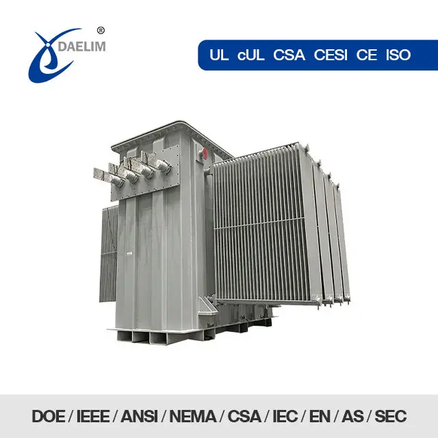
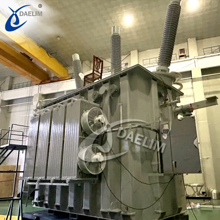
Daelim Transformer is a high-quality transformer supplier that only produces power transformers with 20 years of transformer export experience. There is a professional laboratory to do various experiments on the transformers before they leave the factory to ensure that the transformers received by customers have high mechanical performance and good electrical performance.
Contact Daelim TransformerWhat is power transformer testing?
The power transformer is the most important equipment in the power system. In order to ensure the safe and normal operation of the power system, the transformer must be tested with professional experimental equipment for various mechanical and electrical performances before it leaves the factory and is put into use.
Try for free: Pad Mounted Transformer
What are the testing of power transformer?
![]() The routine test items for power transformers are as follows:
The routine test items for power transformers are as follows:
1. Insulating oil test
2. Measure the DC resistance of the winding together with the bushing
3. Check the voltage ratio of all taps
4. Check the three-phase wiring group of the transformer and the polarity of the single-phase transformer lead wire
5. Measure the insulation resistance of each fastener insulated from the iron core (the connection piece can be disassembled) and the iron core (with an external ground wire)
6. Test of non-pure porcelain casing
7. Inspection and test of on-load voltage regulation switching device
8. Measure the insulation resistance and polarization index of windings and bushings
9. Measure the dielectric loss tangent value tanδ of the winding and the bushing
10. Measure the DC leakage current of the winding and the bushing
11. Transformer winding deformation test
12. AC withstand voltage test of winding and bushing
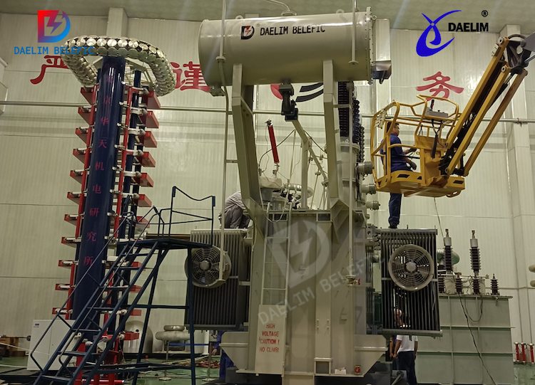
13. Long-term induced voltage test with partial discharge test for winding and bushing
14. Impulse closing test under rated voltage
15. Check the phase.
Other experiments required by customers: such as short circuit experiments, temperature rise experiments, etc.
Learn more: 10.5MVA-13.8/2.4kV Substation Transformer
What is the temperature rise test of the transformer?
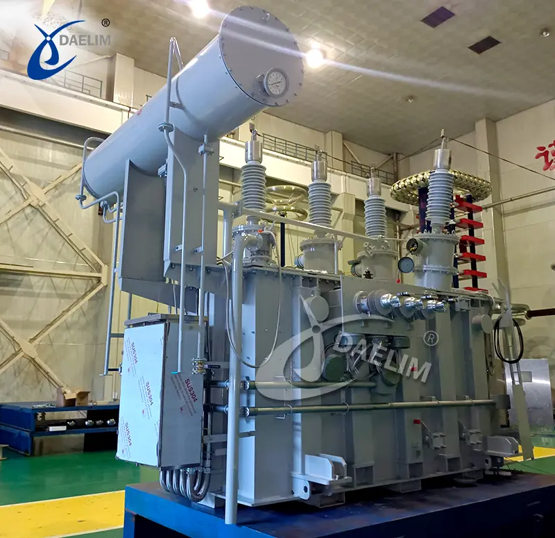
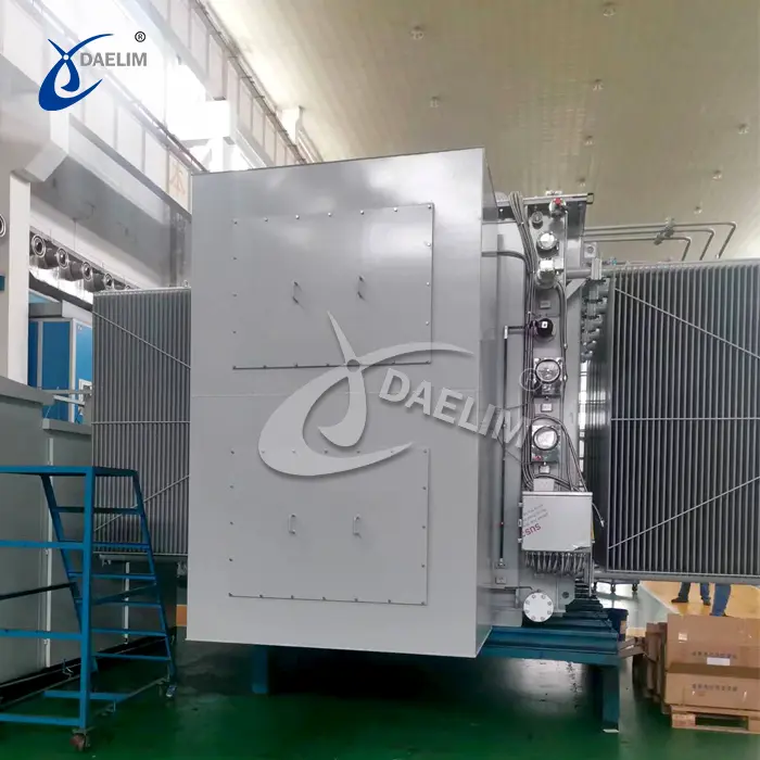
![]() Whether the design of a transformer is reasonable and whether the cooling system is normal can be verified by the transformer temperature rise test. The temperature rise test of a distribution transformer is mainly to detect whether the temperature rise of top oil temperature and high and low voltage windings meet the requirements of relevant standards and technical agreements. The test process is mainly divided into two stages, the total consumption stage and the rated current stage. During the application of the total wear phase, the main purpose is to measure the temperature rise of the oil top layer.
Whether the design of a transformer is reasonable and whether the cooling system is normal can be verified by the transformer temperature rise test. The temperature rise test of a distribution transformer is mainly to detect whether the temperature rise of top oil temperature and high and low voltage windings meet the requirements of relevant standards and technical agreements. The test process is mainly divided into two stages, the total consumption stage and the rated current stage. During the application of the total wear phase, the main purpose is to measure the temperature rise of the oil top layer.
In the second stage, when the measurement of the temperature rise of the top layer is completed, the rated current can be applied for one hour, and then the power supply is quickly cut off, and the short-circuit wiring is opened to measure the resistance value of high and low voltage. Then, based on the above measurement data, the rated frequency rated voltage and rated current of the transformer, the average temperature rise of the low-voltage winding, etc., is effectively calculated.
Read more: How To Choose The Suitable 110KV Power Transformer?
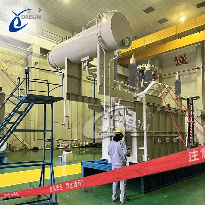
The transformer temperature rise test is the most time-consuming test item, which takes about 12 hours to complete. Through the temperature rise experiment, the quality of the transformer can be known. Since transformers are divided into distribution transformers, substation transformers, main transformers, single transformers, dry transformers, and other types, it is necessary to select a targeted temperature rise test method, so as to ensure the efficiency of the test and the accuracy of the results.
Transformer temperature rise test device
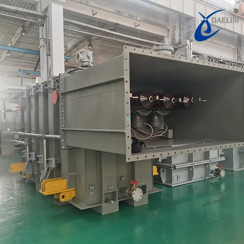
![]() When using the simulated load method to carry out the temperature rise test of the dry-type transformer, it needs to be carried out in steps. The first step is to carry out the no-load test of the transformer, let the core of the transformer heat up, and then carry out the short-circuit test when the temperature is stable. After the temperature is stable, the temperature rise of the winding under the no-load test and the temperature rise of the winding under the short-circuit state of the transformer are measured respectively. Finally, according to the temperature rise of the two stages, the total temperature rise is calculated.
When using the simulated load method to carry out the temperature rise test of the dry-type transformer, it needs to be carried out in steps. The first step is to carry out the no-load test of the transformer, let the core of the transformer heat up, and then carry out the short-circuit test when the temperature is stable. After the temperature is stable, the temperature rise of the winding under the no-load test and the temperature rise of the winding under the short-circuit state of the transformer are measured respectively. Finally, according to the temperature rise of the two stages, the total temperature rise is calculated.
In the no-load temperature rise test, the thermometer is arranged at the point to be measured, and then the iron core is heated due to no-load loss until the temperature is stable. Since the winding does not generate heat during the no-load test, the heat exchange process between the iron core and the winding cannot be effectively displayed, and the measured value is only a reference value and cannot be used as an actual temperature rise for assessment. When the temperature of the iron core is stable, the temperature rise of the winding is measured again.
Get it now: Surplus 15000 kVA transformer for sale!
The measured temperature rise is obtained indirectly by measuring the change in the resistivity of the windings and belongs to the average temperature rise. After the power is turned off, it will first measure a value, then measure a value every 30 seconds, ten times in a row, and then every 10 minutes. The measured value needs to be plotted using semi-logarithmic coordinates, and then the instantaneous thermal resistance value is measured according to the extrapolation method. The short-circuit temperature rise test is carried out after the no-load temperature rise test. The connection method of the short-circuit temperature rise transformer is consistent with the no-load temperature rise test. The low-voltage side is short-circuited and the high-voltage side is powered. After the testing of the test circuit is completed, the rated current is applied to the high voltage side, and the transformer heats up due to the short circuit of the windings. After the temperature rise is stable, the thermal resistance values of the high and low voltage windings are tested.
Finally, the short-circuit temperature rise of the high and low voltage windings is calculated. The test method and calculation method are the same as the no-load temperature rise test. The actual temperature rise of the winding is calculated according to the temperature rise of the high and low voltage windings measured under no-load and short-circuit conditions.
Keep on reading: The Ultimate Guide to 2500KVA Transformer
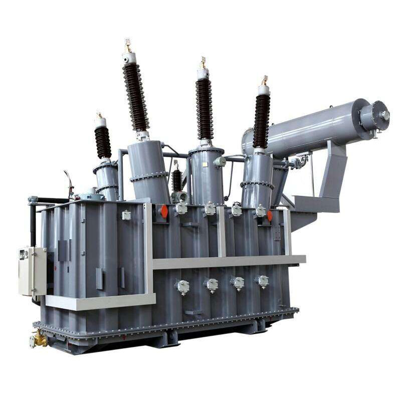
What is the high voltage side of a transformer?
On a conventional step-down transformer, the input terminal is the high-voltage side, and the output terminal is the low-voltage side.
Under normal circumstances, the role of the transformer is to reduce the voltage of the power transmitted by high voltage (saving materials and reducing losses) (there are also boosted ones, which are usually in power plant substations) to meet the normal use standards of electrical equipment.
Transformer high voltage test
In order to ensure the accuracy and authenticity of the high-voltage test results of power transformers, the test content must be selected in strict accordance with relevant regulations. The contents of the power transformer high-voltage test mainly include: insulation resistance measurement, leakage current measurement, dielectric loss factor test, AC withstand voltage test, etc., which will be introduced in detail below.
1. Measurement of insulation resistance
In the high voltage test of power transformers, insulation resistance measurement is the most convenient and simple preventive test. In the measurement of the insulation resistance of the transformer, the overall dampness of the insulation, the degree of overheating and aging, and the pollution can be reflected by the size of the insulation resistance. Taking the insulation resistance measurement of a transformer with a voltage of 110 kV on the high voltage side and a capacity of 31500 kVA as an example, the absorption ratio of the insulation is closely related to the temperature change. decrease, and the absorption ratio of damp insulation will change irregularly. Therefore, in the measurement of the insulation resistance of the transformer, the temperature of the laboratory must be reasonably controlled to ensure the authenticity of the measured value of the insulation absorption ratio.
Learn more now: High Voltage Transformer:Definition,Principle,Uses and Price
2. Measurement of leakage current
In the measurement of leakage current of power transformers, the digital leakage current tester is mainly used for measurement, and its rated working voltage is generally below 2.5kV, which is significantly lower than the rated working voltage of the transformer. If the DC megohmmeter cannot meet the voltage requirements in the test, the test method of adding DC high voltage can be adopted to ensure the accuracy of the transformer leakage current measurement results. In the case of high voltage, if the leakage current of the transformer is significantly higher than the current in the case of low voltage, it indicates that the high voltage insulation resistance of the transformer is smaller than the low voltage insulation resistance, that is, the transformer itself has quality defects, and the anti-leakage function cannot meet the requirements for use.
3. Partial discharge test
The partial discharge test of power transformers is a common "non-destructive" test item. The main test methods are as follows:
(1) Take the power frequency to withstand voltage as the pre-excitation voltage, and reduce it to the partial discharge test voltage. Measure the amount of partial discharge;
(2) Use the overvoltage in the simulated operation as the pre-excitation voltage to reduce the partial discharge test voltage for 1 to 1.2 hours to measure the partial discharge.
The second test method can measure whether the partial discharge phenomenon occurs under the long-term working
voltage of the transformer, so as to ensure the safe operation of the power transformer in the application. In addition, in the partial discharge test of the power transformer, the design of the insulation structure, the withstand field strength of the insulating medium, the surface field of the live and ground electrodes, the processing and processing of the insulating parts, etc. should be considered so that the partial discharge amount is less than the specified value, rather than The main basis is whether the main and longitudinal insulation is discharged.
In the partial discharge test of the power transformer, when the power frequency withstands voltage is used as the pre-excitation voltage, the duration of the test voltage is about 15 minutes. Properly extending the voltage duration of the partial discharge test has a certain effect on the insulation performance test. If The insulation performance of the transformer is not ideal, which may cause different degrees of destructive damage. When the overvoltage in the simulated operation is used as the pre-excitation voltage, the standard requirement for the voltage duration of the partial discharge test is 1h, and how long the transformer can withstand the pre-excitation voltage is closely related to the volt-second characteristic of the insulation structure.
Read more: Basic Guide Of Electrical Transformer
In the partial discharge test of the power transformer, the partial discharge amount is usually related to the field strength on the surface of the live and grounded electrodes, but not to the frequency of the power supply. Therefore, the noise at the test site should be controlled as much as possible, and the partial discharge amount of the power supply should also be isolated.
4. Transformer ratio measurement
![]() The transformation ratio measurement methods of power transformers mainly include the dual voltmeter method, transformation ratio bridge method, etc. Among them, the transformation ratio bridge method is a commonly used method in field tests. It mainly has the following advantages: it is not affected by the stability of the power supply high accuracy and sensitivity; error can be read directly: the test voltage can be adjusted, which is relatively safe. In the transformation ratio test of power transformers, the test of continuous groups can also be completed synchronously, and the same wiring group is one of the basic conditions for the parallel operation of transformers. Therefore, judging the wiring group of power transformers is also a high-voltage test. an indispensable item. Commonly used test methods are the AC voltmeter method, phase table method, transformer ratio bridge method, DC induction method, group table method, etc. The group table is a common special instrument for testing the group, phase sequence, and polarity of power transformers.
The transformation ratio measurement methods of power transformers mainly include the dual voltmeter method, transformation ratio bridge method, etc. Among them, the transformation ratio bridge method is a commonly used method in field tests. It mainly has the following advantages: it is not affected by the stability of the power supply high accuracy and sensitivity; error can be read directly: the test voltage can be adjusted, which is relatively safe. In the transformation ratio test of power transformers, the test of continuous groups can also be completed synchronously, and the same wiring group is one of the basic conditions for the parallel operation of transformers. Therefore, judging the wiring group of power transformers is also a high-voltage test. an indispensable item. Commonly used test methods are the AC voltmeter method, phase table method, transformer ratio bridge method, DC induction method, group table method, etc. The group table is a common special instrument for testing the group, phase sequence, and polarity of power transformers.
5. Dielectric loss factor test
In the high-voltage test of power transformers, the dielectric loss factor test is one of the basic insulation preventive test items. The main purpose of the test is to determine the insulation performance of the transformer according to the size of the dielectric loss factor. In the normal operation of the transformer, the change of the dielectric loss factor is closely related to the size of the insulation loss. In the test process, the test personnel can grasp the overall moisture and deterioration degree of the transformer insulation through the relevant results, so as to obtain accurate test results.
Try for free: Skid Mount Transformer Solution With 3 Phase Pad Mounted Transformer Inside
In the dielectric loss factor test of power transformers, the results are significantly better than the insulation resistance measurement and leakage current test, mainly because during the test process, the correlation with factors such as the test voltage and equipment size is small, and the test personnel can accurately judge. Transformer insulation changes.
6. AC withstand voltage test
The AC withstands voltage test of power transformers is mainly used to identify the size of its insulation strength. The use of this test method can directly reflect the centralized performance defects of the transformer, so as to ensure the improvement of the insulation performance of the transformer and avoid serious damage caused by insulation aging. security incident. Before the AC withstands the voltage test of the power transformer, the insulation resistance, leakage current, dielectric loss factor, etc. of the voltage transformer must be carefully measured. After obtaining the relevant test results, the AC withstand voltage test can be organized. If the statistics and calculation of the relevant test results are unreasonable, it will directly affect the accuracy of the AC withstand voltage test results.
Learn more about Transformer Test
Safety Design Method for High Voltage Test of Power Transformer
In the high-voltage test of power transformers, due to the large test voltage required, if an effective safety design method cannot be adopted, it will directly affect the accuracy of the test results and the safety of the test personnel. Therefore, in the process of high-voltage test of power transformers, we must pay attention to the research and application of safety design methods, so as to ensure the smooth development and progress of the test work.
1. Prevent induced voltage and discharge counterattack
In the high-voltage test of power transformers, effective measures to prevent induced voltage must be taken between the test equipment and other equipment. Usually, the test equipment and other instruments and equipment are short-circuited and grounded reliably. In the high-voltage laboratory, a dedicated short-circuit grounding well and grounding system should be set up according to the test requirements, and the various capacitor equipment that is idle in the laboratory should also be short-circuited and grounded according to the requirements.
Read on: How Much You Know For The Different Types Of Transformers?
Since the high voltage test of the power transformer is carried out in a closed six-sided shielding environment, there may be instantaneous discharge during the test. Therefore, the high-voltage cables in the laboratory must be protected by metal pipes and buried in the ground. Under normal circumstances, the length of the metal protection tube should be > 15 m, and it should be connected to the ground electrode every 5 m, so as to strictly control the occurrence probability of the discharge counterattack phenomenon.
2. Reliable grounding
In the high-voltage test of power transformers, it is necessary to ensure that the grounding system of the laboratory is good, and the grounding resistance generally needs to be below 0.5Ω, so as to ensure the safety of test equipment and test personnel. In the case of good grounding conditions, the laboratory should also be regarded as a special equipotential body, and the shells of all metal instruments and equipment in the laboratory should be well grounded, especially between the transformer and the test equipment. There are reliable, safe, and stable metal connections. In the high-voltage laboratory, the location of the grounding point should be clearly marked to prevent people from getting an electric shock during the test.
3. Fireproof and explosion-proof
In the high-voltage test of power transformers, it is necessary to strictly prevent the overload or short circuit of the transformer during operation. Special attention should be paid to the decomposition and expansion of insulating materials, insulating oil, etc. due to high temperature, electric sparks, and other factors, resulting in gasification, resulting in transformers. The internal pressure increases sharply, which may cause the transformer casing to explode, causing a large amount of insulating oil to be ejected and burned, and the oil flow will further increase the risk of fire. Therefore, in the high-voltage test process of power transformers, we must pay attention to the prevention of safety problems to ensure the safety of the test.
Read more about Fire Prevention System for a set of power transformers
In short, the high-voltage test of power equipment is a high-tech and complex project. In the high-voltage test of power transformers, reasonable test conditions, methods, and contents must be selected, and attention should be paid to the safety design during the test process to ensure the smooth progress of the test operation. , obtain the corresponding test data, and then scientifically determine the comprehensive performance of the transformer.
Custom Power Transformers
Daelim Transformer Factory has a professional team of transformer engineers, who can design HV transformers, distribution transformers, pad mounted transformers, dry transformers, and other transformers according to your needs and technical requirements. If you have any questions, please feel free to contact Daelim.
Related Products


Related Article
230 kV Three Phase Power Transformer For USA Market
In 2023, Daelim Transformer designed and manufactured a cutting-edge 230 kV three-phase power transformer for a client in Nevada, USA. The client recently shared installation and operational photos, showcasing the successful deployment of this remarkable transformer. Let's delve into the specifics of this transformer project!
Canadian 69 kV Substation Transformer Project
Today, we are excited to present a case study on a 69 kV substation transformer project by Daelim Transformer. Our Canadian client required a step-down transformer for their substation to connect with the hydroelectric grid in Quebec.
20MVA Power Transformer for the United States
This project involves the development of a 20 MVA three-phase power transformer tailored for the United States market. The primary voltage is 24.94kV, and the secondary voltage is 4.16kV, indicating it functions as a step-down transformer. The design and production fully comply with IEEE C57.12.00 standards and have passed third-party UL team testing. All accessories also adhere to IEEE standards. FR3 vegetable oil serves as the insulating liquid for the transformers.