Ultimate Guide To Power Transformer Diagrams
A power transformer diagram is a schematic representation that shows the different parts and electrical wires of a transformer.
Daelim Transformer is a reputable transformer manufacturer that meets international standards. DB Transformer's transformers are certified by UL/cUL. Whether you require an HV power transformer, pad mounted power transformer, pole mounted transformer, or substation power transformer, DB Transformer can fulfill your requirements.
Let's delve into an electrical diagram of a transformer while also defining a power transformer drawing. We will explore single-phase transformer connections, the diagram of a 3-phase power transformer, and the components of a power line transformer diagram.
Contact Daelim
What Is A Power Transformer Diagram?
A power transformer diagram demonstrates an illustration of an electric transformer's power interconnections and subsystems. It serves as a visual guide that assists in comprehending how the transformer's internal framework has been set up and where its accessories are generally positioned.
With regards to a power transformer diagram, there are two windings. These two main wires frequently appear in schematics as loops or collections of interconnecting lines.
What Does A Transformer Electrical Diagram Show?
A transformer electrical diagram exhibits how electricity connects and the essential elements of a power transformer. Let's take a look at what is displayed in the distribution transformer diagram, residential transformer diagram, single phase transformer diagram, and power transformer diagram.
Distribution Transformer Diagram

This distribution transformer diagram, created by Daelim, showcases a 400 kVA transformer with a high voltage of 11kV and a low voltage of 0.416kV. The diagram provides essential information, including
- Project name;
- Transformer dimensions, weight details (core and coil, oil, and total weight),;
- Component locations and names;
- HV and LV schematic diagrams;
- Manufacturer details like name, address, and contact information.
It serves as a comprehensive visual reference for understanding the transformer's specifications and layout.
Learn more about Distribution Transformer
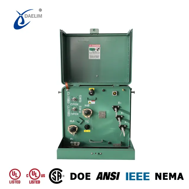
Residential Transformer Diagram

Daelim presents a residential transformer diagram with the following information:
- Transformer dimensions
- Transformer technical data including:
- Rating
- Primary Voltage
- Secondary voltage
- Frequency
- Polarity
- Winding material
- Efficiency
- No-load losses
- On-load losses
- Impedance
- Altitude
- Color
- Transformer weight breakdown:
- Tank and accessories weight
- Total oil weight
- Total weight of the transformer
- Parts list with numbers and marked accessory positions
This diagram provides comprehensive information about the residential transformer's dimensions, technical specifications, weight distribution, and component positioning.
Try for free: Residential Transformer: The Small Green Box in the Neighborhood
Single Phase Transformer Diagram

The single-phase transformer diagram below displays the following information:
- Transformer dimensions
- Transformer weight breakdown: oil weight, active part weight, and total weight
- Transformer capacity
- Low voltage specification
- No-load loss
- On-load loss
- Total loss
- Parts list with quantities
- High voltage bushing
- Low voltage bushing
- Nameplate
- Support lug
- Tap changer
- Pressure relief valve
- Cover clamp
- Lifting lug
This diagram provides a clear overview of the single-phase transformer's dimensions, weight, capacity, voltage, losses, and various components such as bushings, tap changer, and nameplate. It serves as a helpful reference for understanding the transformer's specifications and identifying its key parts.
Reading more about Single Phase Transformer
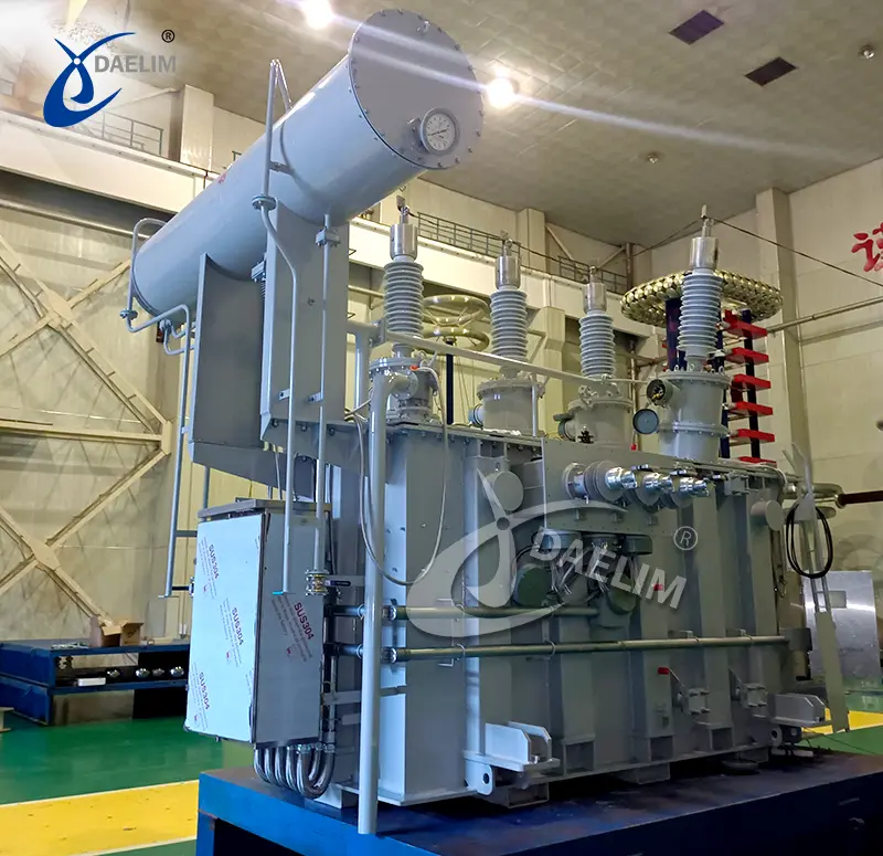
Power Transformer Diagram

The figure below is the 66kV 12MVA power transformer diagram designed by Daelim for the Australian market. The Power transformer diagram mainly includes the following information:
- Power transformer weighs
| Tank and accesories |
| Total oil weight |
| Total weight |
- Power transformer dimensions
- Power transformer technical data
| Rating | Winding material |
| Primary Voltage | Load loss at rated voltage |
| Secondary voltage | No load losses |
| Frequency | Impedance |
| Vector group | No. Of tap position |
- Fittings and description
| hv bushing | 3 | pressure relief device | 1 |
| hv bushing ct | 3 | Pressure/vacuum gauge | 1 |
| Welded cover | 1 | Ground copper bar |
|
| Radiators | 7 | Liquid level gauge | 1 |
| SS ground pads | 2 | Lifting lugs | 4 |
| Terminal box | 1 | Low voltage cable box | 1 |
| nameplate | 1 | LV BUSHING | 4 |
| tap changer | 1 | CT box | 7 |
| ladder | 1 | Explosion-proof wire way | 3 |
| Winding temperature indicator | 1 | Oil sample valve | 3 |
| Dial type thermometer | 1 | Butterfly valve | 14 |
| Core Ground Bushing Assembly | 1 | Drain valve | 1 |
- Power transformer type
You may enjoy: Basic Guide To High Voltage Power Transformers
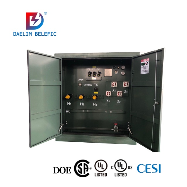
How Is A Residential Transformer Diagram Different?
In suburban settings, a residential transformer diagram can convert 7000 volts of electricity into either 150 or 250 volts. Typically, this size of a residential transformer diagram is responsible for supplying power to one to three small businesses or around 10 to 15 residences.
A residential transformer diagram's secondary portion illustrates how power is highly distributed throughout the house. Usually, it displays connections to the core transmission panel or transmission board, where power is further divided into separate circuits for branching. Several domestic loads, including light circuits, outlets, equipment, and HVAC systems, are generally shown in the residential transformer diagram.
Overall, conventional power transformer diagrams are technically applied for high-power distribution and transmitting networks. Meanwhile, residential transformer diagrams are more involved with the operational setups of home power systems.
You may enjoy: Pad Mounted Transformer
How To Interpret A Power Transformer Drawing?
Understanding the symbols, labels, and standards often used in electrical engineering drawings is necessary to read a power transformer drawing.
Here are the essential actions to take:
Step 1: Gather information.
To interpret a power transformer drawing, examine the title block, which normally contains the classification of the transformer, details about the manufacturer, and the drawing number.
Step 2. Recognize the symbols.
Acquaint yourself with the electrical sketching symbols of a power transformer drawing. Transformers are frequently represented by a rectangle with two parallel lines within, which stands in for the main core, and by letters or numbers, which denote the winding terminals.
Step 3. Identify the components.
Locate the important parts on a power transformer drawing. These include connectors, tap changers, bushings, core, and windings. The labels and notes that describe the various elements should be carefully read.
Step 4. Verify additional features.
It will be depending on the complexity of the power transformer. There can be additional parts or features included in the power transformer drawing.
Examples include safety measures, wiring for controls, grounding connections, and auxiliary gear. Pay close attention to labels and legends to determine what they mean.
Step 5. Follow electrical connections.
Follow the electrical connections between the bushings, taps, and other parts, and the windings. To comprehend how electrical circuits are generally connected, pay great attention to the terminal labels and numbers.
Step 6. Refer to documentation.
If you encounter any strange symbols, marks, or notations, refer to the documentation of the power transformer drawing. In general, you can find this in the form of transformer manuals or electrical standards, to improve your understanding.
What Are Single Phase Transformer Connections?
 Typically, single phase transformer connections have a common magnetic core with main wirings and secondary cables. To produce particular transformations of current, the single-phase transformer connections can be set up in a variety of ways. The most standard and typical configuration is a single-phase, two-winding transformer. One of three connections is generally made to the main wirings:
Delta connection: The ends and margins of the wires link together to make a closed circuit.
Wye connection: One end of each winding connects to create a neutral, while the other ends are usually attached to the input voltage source.
Open delta (V-connection): When a delta wiring scheme uses only two wires, the power rating is lower than whenever a full delta arrangement is in place.
Reading more about Transformer Connection
How Does A 3 Phase Power Transformer Diagram Work?
By examining the 3 phase power transformer diagram, engineers may understand how the phases and wires are mainly connected. They can use it for studying the distribution of power, current circulation, and voltage shifts in a three-phase system. This knowledge is essential for designing, operating, and troubleshooting 3-phase power transformer diagram systems.
The two simplest methods used to link the three main windings, represented by the letters H1, H2, and H3 (or L1, L2, and L3), are in a delta () or wye (Y) configuration. The degree of phase displacement in a 3-phase power transformer diagram generally ranges from 0 degrees or 180 degrees across each primary energy source and its associated secondary coil.
What Distinguishes A Single Phase From A 3 Phase Transformer Diagram?
In a single phase diagram, electricity passes through a neutral wire and a power wire. In contrast, the three power wires of a 3 phase power transformer diagram are in charge of transferring the load.
One neutral wire and one conductor are generally used in single-phase systems.
In most cases, in a 3-phase power transformer diagram, three conductors and one neutral wiring are frequently applied.
What Does A Distribution Transformer Diagram Represent?
The four main components that make up a distribution transformer diagram are the source connection, outlet link, cables or wires, and its core. The specific design of a distribution transformer diagram components varies on the type of transformer to use.
Typically, single-phase transformers are set up in a wye shape and supplied with 1 to 2 bearings. These basic sections can be generally used to create three or four-wire wye distinctions if they have been properly organized.
Usually, inside a distribution transformer diagram, the core materials are shaped like an E or C, made of metal straps and laminated sheets. In a steel tank filled with resin, the entire assembly is specifically housed.
When Having Issues With A Power Transformer Diagram, How Can You Troubleshoot It?
A power transformer's performance can be greatly affected by a variety of problems. Using a power transformer diagram as a guide, you can troubleshoot some issues. Using a power transformer diagram, adhere to the correct electrical safety precautions, such as donning the required safety gear and working on de-energized equipment.
Next is to see to it that the distribution transformer diagram is always inspected. Examine the device for any glaring indications of damage, such as burn marks, excessive heating, oil leaks, or loose connections. Then verify the single-phase transformer connections like the input power supply. Check if it is stable and falls within the permitted range.
You must also gather a mineral oil sample, and then send it to a lab for analysis. Oil analysis of a power transformer diagram can reveal important details about pollutants, moisture content, and the state of the insulating material.
In the next part, use an infrared camera to do a thermographic inspection. This aids in finding any hotspots in the power transformer electrical diagram, which may be mainly caused by faulty connections, overloaded parts, or other problems and result in excessive heat.
Lastly, look over the manufacturer's documentation, including any technical or user manuals for the transformer. Search for any troubleshooting instructions, specifically for 3 phase power transformer diagram or a single-phase transformer connection.
Overall, it is essentially advisable to seek the assistance of a licensed electrical engineer if you run into difficult problems in your transformer electrical diagram.
How Does A Power Line Transformer Diagram Work?

In a power line transformer diagram, a wire's electric current is highly produced when the magnetic field around it changes. Therefore, if we place a coil of wire next to the first one and apply a fluctuating electric voltage to the first coil, the second wire will also experience an electric current.
Because the current in the first coil induces the current in the second coil, this phenomenon is generally known as electromagnetic induction. The vital line that supplies electricity to your home is at last in reach.
Beyond a normal home, a string of poles carries a ground wire and a single phase of power through the power line transformer diagram. However, in some areas, there may be 2-3 stages on the pole subject to where the house is typically positioned in the distribution grid.
Learn more about Power Line Transformer
Why Are Power Transformer Diagrams Important?
Power transformer diagram is very important because they provide visual images of a transformer and its parts. A transformer electrical diagram assists consumers by clarifying the transformer's configuration, connections as well as and operations.
During the installation and maintenance processes, the power transformer diagram acts as a guide. They offer a precise illustration of the wiring, linkages, and internal and external connections of the conventional transformer.
To ensure accurate installation, proper wiring, and respect for safety regulations, technicians can consult the transformer electrical diagram. Using power transformer drawing as a guide, technicians can more quickly detect issues by analyzing the transformer's connections and design.
Overall, they assist technicians in comprehending suitable safety precautions, suitable grounding, and suitable connecting techniques. The risk of electrical mishaps is highly reduced by following the schematic within the predetermined parameters and complying with safety regulations.
Is It Possible to Alter A Transformer Electrical Diagram?
Yes, it is possible to modify a transformer electrical diagram, but you should proceed carefully and with the right knowledge. It is essential to involve skilled electrical engineers or experts with knowledge of transformer design, electrical circuitry, and pertinent standards and laws.
They can precisely determine how the suggested changes will affect things and make sure the power transformer diagram adheres to performance and safety standards. Remember that the modifications shouldn't compromise the electrical system as a whole, the transformer's functionality, or the safety of the people.
In that case, it should be always pointed out that altering a transformer electrical diagram without the appropriate knowledge might result in risks to safety, functional problems, and system failures.
Daelim Is Your Advisor When It Comes To Power Transformer Diagram
When it comes to navigating the intricacies of power transformer diagrams, you need a reliable advisor by your side. That's where Daelim comes in.
When you discover the potential of power transformer diagrams, your understanding of electrical components may significantly shift. With Daelim as your advisor, you'll gain invaluable insights into the inner workings of transformers, allowing you to optimize performance, ensure safety, and streamline operations.
Daelim provides a wealth of materials, manuals, and tools to make sure that you have the awareness and self-assurance to handle any challenge when it comes to power transformer diagrams.
Related Products


Related Article
Power Transformer Manufacturers Around the World
In this article, we will tackle the top power transformer manufacturers around the world including snippets of the most powerful transformer and a short guide on how to choose a power transformer manufacturer.
Transmission Transformer | At The Power Lines Core
Transmission transformers also known as power transformers are primarily used for power transmission and can also be used as a power receivers.
CSA C802 For Minimum Efficiency Values For Power Transformers
The Canadian Standards Association has issued and produced CSA C802 as a national standard and policy for the country. This policy explicitly shows the performance and efficacy levels of power transformers rated from 501 to 10000 kVA.