Guide to Pad Mounted Transformer Fuse
In the Americas, Pad mounted transformers are primarily utilized in underground power distribution systems, making them essential electrical components in these systems. These transformers may encounter voltage instability during operation, potentially leading to overcurrent or short circuit conditions. Consequently, safeguarding the transformer from overcurrent damage becomes paramount, with fuses playing a crucial role in this aspect.
This article will delve into pad-mounted transformer fuses, exploring what fuses are and how they function. We will discuss the types of fuses required for pad-mounted transformers and guide on selecting the appropriate fuse for your specific needs. Furthermore, readers will gain insights into the functions and advantages of fuses used in pad-mounted transformers.
Contact Daelim TransformerWhat is a fuse?
A fuse serves as an electrical safety device composed typically of zinc, copper, silver, aluminum, and other metals with low melting points. When a circuit experiences excessive current flow, the fuse melts, breaking the circuit and safeguarding other devices from damage. Its primary function is to provide overload protection, constituting an integral part of the power distribution system.
How do pad mounted transformer fuses work?
Pad-mounted transformer fuses function much like standard fuses. When the current within the pad-mounted transformer becomes too high, the fuse's resistance generates heat. If this heat surpasses the fuse's dissipation capability, the fuse's temperature rises. Once it reaches or exceeds the fuse's melting point, the fuse self-fuses, disconnecting the circuit to shield the transformer and load equipment from harm.
Learn more about Pad Mounted Transformer
What types of fuses are used for pad mounted transformers?
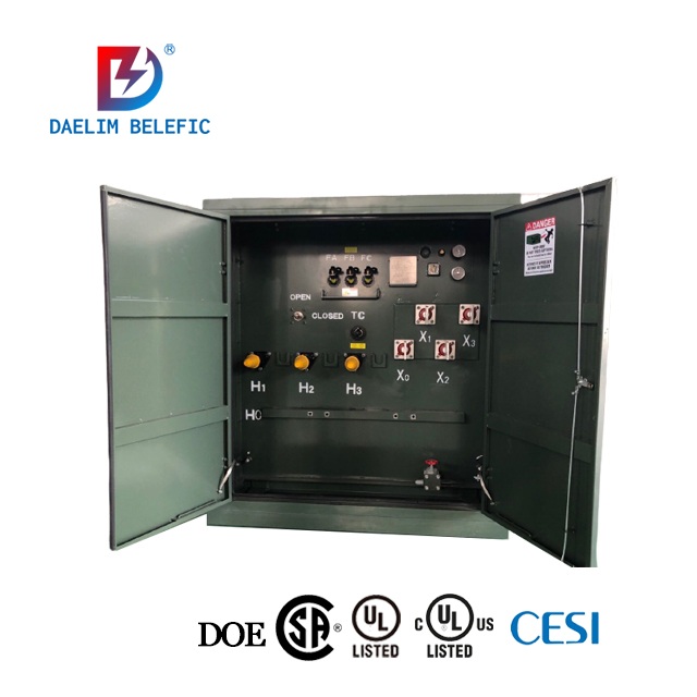
Pad-mounted transformers are equipped with a two-fuse protection system.
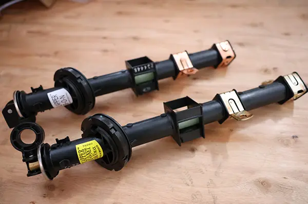
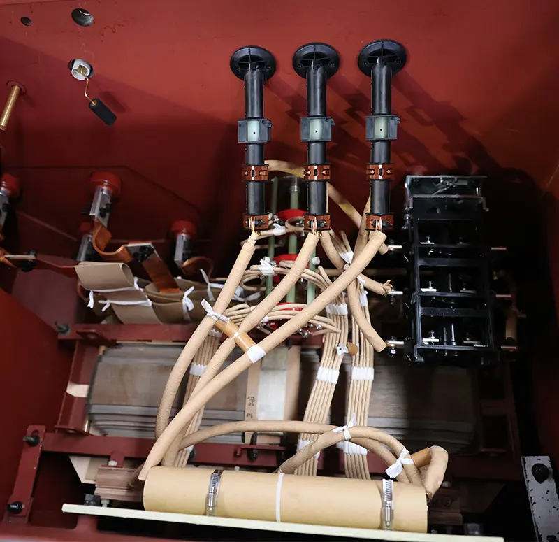
Bay-O-Net Fuse
Overload and secondary fault protection
The Bay-O-net-fuse acts as a dual-sensitive fuse, safeguarding against short-circuit faults on the secondary side of the transformer. Designed for overload protection, it is easily replaceable and offers a rated current typically 1.5-2 times higher than that of the transformer. This fuse reacts promptly to excessive currents, ensuring the protection of connected load equipment. It is commonly paired in series with a backup current-limiting fuse or isolation link for comprehensive protection.
Current-Limiting Fuse—Internal Fault Protection
The backup current-limiting protection fuse (ELSP) is employed to shield against faults occurring within the box transformer, primarily safeguarding the high-voltage side. In the event of critical conditions such as internal short circuits or lightning-induced overcurrents, backup current-limiting fuses offer essential protection by isolating the faulty transformer from the remainder of the healthy distribution system. By promptly interrupting the circuit, these fuses mitigate the risk of further disruptions and potential collateral damage to the transformer and its surroundings.

The current-limiting fuse is specifically designed to address internal faults within the box transformer, with its rated current typically set at 3-4 times the transformer's rated current. Installed within the fuel tank, replacing this fuse necessitates the opening of the fuel tank cap and draining of the oil, a process more intricate than bayonet fuse replacement. In instances of high current demands, the option of installing two parallel fuses per phase exists, albeit at the expense of increased space requirements.
It is crucial to note that current-limiting fuses are not primarily intended to protect the transformer itself but rather to prevent electrical fires and explosions resulting from a malfunctioning transformer. Once a current-limiting fuse operates, it typically indicates a failure within the transformer.
Several key considerations guide the selection of a current-limiting fuse. These include the voltage rating, interrupting rating, and the fuse's continuous ampere rating. Attention to these factors is imperative to ensure proper fuse functionality and prevent premature operation. Additionally, coordination with line and load-side protection devices is essential to enable selective shutdown and mitigate the risk of adverse consequences.
While bayonet fuses are adept at managing lower overload currents, current-limiting fuses are better equipped to handle higher currents. Typically, by the time a transformer requires the intervention of a current-limiting fuse, significant damage may have already occurred.

Isolation Link
The isolation link, is employed in conjunction with Bay-O-Net fuses and Magnex® interrupters when there is no current-limiting fuse connected in series. Its purpose is to provide additional protection in the event of an internal transformer failure, as well as during refusal and switching operations.
In instances where the transformer is relatively small and operates at low voltage with a correspondingly low available short-circuit current, the bayonet fuse alone may offer adequate overcurrent protection without the need for a current-limiting fuse. However, in such cases, an isolation link is indispensable when used alongside a bayonet fuse. Its role is to create a physical break in the circuit if the transformer fails, preventing electrical workers from inadvertently re-energizing a faulty transformer by simply replacing the bayonet fuse.
While both the isolation link and the current-limiting fuse share the common objective of safeguarding against short-circuit faults within the box transformer, their operational disparities should be noted. In the event of fusion, the isolation link may introduce contamination to the transformer's insulating oil and impurities, unlike the current-limiting fuse. The latter's construction involves mounting components within fiberglass-reinforced resin tubes with copper-plated contact caps, ensuring optimal strength. These tubes are filled with high-purity silica sand, with series arcs generated at the neck point of the original component. As these arcs interact with the constraining medium, they introduce rapidly rising resistance into the fault circuit, significantly reducing the peak value of the current wave. Notably, all arc extinguishing actions occur within the fiberglass resin tubes, minimizing the risk of contamination or damage to the transformer's insulating oil and components.
Pad mounted transformer design engineers meticulously coordinate protective devices to ensure comprehensive protection against various overcurrent conditions while maintaining the transformer's reliable operation. In summary, a well-coordinated fusing scheme in panel transformers provides holistic protection, with each protective device serving a distinct role in safeguarding both the transformer and the broader electrical system.
What caused the pad mounted transformer fuse to blow?
 The bayonet fuse and backup fuse together form the protection system of the pad-mounted transformer, playing vital roles in primary and secondary protection, respectively.
- Overload: When the load of the pad-mounted transformer exceeds the overload limit of the transformer, excessive current may cause the fuse to blow. This situation typically arises due to the connection of too many load devices to the pad-mounted transformer or a sudden surge in power demand. During such instances, the primary defense mechanism of the pad-mounted transformer, the bayonet fuse, will fuse for protection.
- External short circuit: This may occur due to the failure of electrical equipment connected to the front end of the pad-mounted transformer or a circuit malfunction. In such cases, the bayonet fuse serves as the initial protective barrier.
- Internal short circuit or pad-mounted transformer failure: When a fault occurs within the pad-mounted transformer, the backup fuse serves as the final line of defense. Upon detecting excessive current flow through the pad-mounted transformer, these backup fuses disconnect the transformer from the electrical grid, preventing further damage.
Is the pad-mounted transformer to be equipped with only one fuse per phase?
The answer is not absolute. We will see that there are six or nine bay-O-net fuses in the high-voltage compartment of some 3 phase pad mounted transformer. This is determined by the current in the pad-mounted transformer. If the current is too large, the customer requires that the bay-O-net fuse must be equipped. Multiple fuses will be used in parallel. However, when designing the pad-mounted transformer, Daelim Transformer engineers tried their best to design it as a single fuse for each phase. Because if multiple fuses are installed in one phase, the risk of failure and repair will increase.
Does a pad-mounted transformer have to be equipped with fuse protection system?
 Not all pad-mounted transformers require fuse protection. There are specific scenarios in which a pad-mounted transformer may not need fuse protection:
- If the external circuit already incorporates protection equipment such as circuit breakers and high-voltage load switches, then the pad-mounted transformer may not necessitate a fuse protection system.
- In cases where the capacity of the pad-mounted transformer is excessively large and the voltage is too high, rendering the matching of a fuse protection system impractical due to the heightened current levels, fuse protection may not be necessary. However, external protection measures must still be provided.
Conclusion
In conclusion, the pad-mounted transformer equipped with a two-fuse system plays a crucial role in safeguarding both the electrical system and the equipment itself. Daelim Transformer's engineering team possesses extensive professional knowledge and project experience, enabling them to provide the optimal fuse protection system for your pad-mounted transformer. For any inquiries regarding pad-mounted transformer fuses or project support, please do not hesitate to Contact the Daelim Transformer Team.
Related Products
Related Article
2550 kVA Pad Mounted Transformer For Data Center in Mexico, Missouri
Today, we're excited to showcase Daelim Transformer's involvement in a project supplying four 2550 kVA pad mounted transformers tailored for a data center located in Mexico, Missouri. Data centers, known for their substantial power demands, require reliable solutions to ensure seamless operation during peak electricity usage.
2000 kVA Pad Mounted Transformers for Canadian Utility
Daelim Transformer is pleased to announce its contribution to a utility project in Toronto, Canada, involving the supply of two units 2000 kVA pad mounted transformers. These transformers are integral to enhancing the power infrastructure in the region. The project demands adherence to CSA standards, with a stringent delivery deadline of 10 weeks to meet the urgent needs of the client.
Supply of 37.5 kVA Single Phase Pad Mounted Transformers for Canadian Utility
Today, we are excited to introduce a project undertaken by Daelim Transformer aimed at supplying transformers to a Canadian utility. This project involves the delivery of 80 units of 37.5 kVA single-phase pad mounted transformers, specially designed to meet the utility's requirements. With a high voltage (HV) rating of 24940GRDY/14400 V and a low voltage (LV) rating of 240/120 V, these transformers are vital components in the utility's infrastructure.
1750 kVA Pad Mounted Transformer for the Dominica Market
Today, we're excited to present a transformer project tailored for the Dominican market. Our 1750 kVA pad mounted transformer is designed to meet the specific requirements of our clients in Dominica. This step-down transformer boasts a primary voltage of 13.8 kV and a secondary voltage of 480Grdy/277V, adhering to the IEEE C57.12.34 standard. With its robust features and reliable performance, this transformer is set to enhance the power distribution infrastructure in Dominica.
2600 kVA Pad Mounted Transformer for Blcokchain
Daelim Transformer successfully provided three customized 2600 kVA pad mounted transformers to power a state-of-the-art blockchain facility in Texas, USA. Our transformers were meticulously designed to meet the unique demands of the mining operation, ensuring seamless power distribution with unwavering reliability and efficiency.
2 MVA Pad Mounted Transformer for Utility
Behold the backbone of Canada's utility infrastructure—the 2MVA pad mounted transformer. With a primary voltage of 4160Grdy/2400V and a secondary voltage of 800GrdY/461V, this transformer stands as a testament to efficiency and reliability in power distribution. Crafted in strict accordance with CSA standards and CAN/CSA802.1 energy efficiency guidelines, it embodies the pinnacle of engineering excellence.