Transformer Calculation Table
Our current electricity distribution system is very sophisticated and electrical transformers are the backbone of this electricity distribution system. Whether you want to step up or step down the provided voltage, electric Transformers are the only electrical device that can do this task for you.
In order to make the Electrical Transformer capable of regulating the electrical voltage for the consumption, it is important to perform proper Transformer calculations based on the consumer requirement. It is also important to consider the international standards that regulate the Electrical Transformer design during the Transformer design calculation stage.
This article is all about exploring the key Transformers specifications, understanding the essential formulas and having a comprehensive understanding of Transformer sizing methods by providing some examples. To have a proper view of the Transformer design stage, we will also present a Transformer calculation table for our readers to have a comprehensive overview of the procedure.
Contact Daelim TransformerUnderstanding Transformer Specifications
Before starting work on the Transformer calculation table, you need to understand the specific Transformer specifications that are widely used in all types of transformer calculation during the Transformer designing stage. Following are the five main Transformers specifications that you need to know before you start the Transformer calculations stage.
Transformer voltage
The first and the most important thing you need to know is the electrical voltage that the Transformer will be regulating during its normal or average working load. You need to know the input voltage of the Electrical Transformer also known as the primary voltage and the output voltage from the Transformer needed for your specific application also known as the secondary voltage.
Power rating
The second thing you need to know about the Transformer specification is the Transformer power rating against which you will be designing your Electrical Transformer. Electrical Transformer power is the product of the transformer voltage and the current that is being either supplied or drawn from the electrical current. The power rating of an Electrical Transformer is usually represented in Kilo Volt Ampere or in large applications Mega Volt Ampere.
Frequency
Electrical Transformers are designed and developed to deliver alternating current and alternating voltage. The alternating current and alternating voltage have a specific frequency at which it can be transmitted so you need to know the exact frequency at which you will be regulating the electrical voltage and current. Depending on the standards and requirement of the specification, you can either have 50 hertz or 60 hertz frequency for your alternating current.
Current (amperes)
You also need to know the maximum possible current that your Electrical Transformer will be processing based on the specific needs of the application against which the Electrical Transformer is being designed. It is important to know the maximum current that will flow through the Electrical Transformer as electrical current above the maximum limit will potentially damage the internal parts of the Electrical Transformer.
Impedance (%)
Other factor that you need to consider is the impedance of the Electrical Transformer during its design calculation stage, because this impedance defines the internal resistance that is offered to the current as it flows in the Electrical Transformer winding and it also defines the impact voltage regulation associated with the Electrical Transformer design.
The Transformers specification mentioned above are fundamental because they dictate the Transformer performance and its suitability for the specific application and they also verify the compliance with electrical codes and international standards associated with Electrical Transformer design.
Essential Transformer Calculation Formulas
We will present you all the essential Transformer calculation formulas and in order to make the best out of your time, we will be presenting formulas in single phase and three phase configurations so that you can understand how to perform Transformer calculations for single phase electrical Transformers and for three phase Electrical Transformer.
Transformer Power Rating (Single Phase)
If initially you are provided with the Electrical Transformer voltage and the current required by the application, then you can perform a simple set of calculations to get the Transformer power rating required to support the given application.
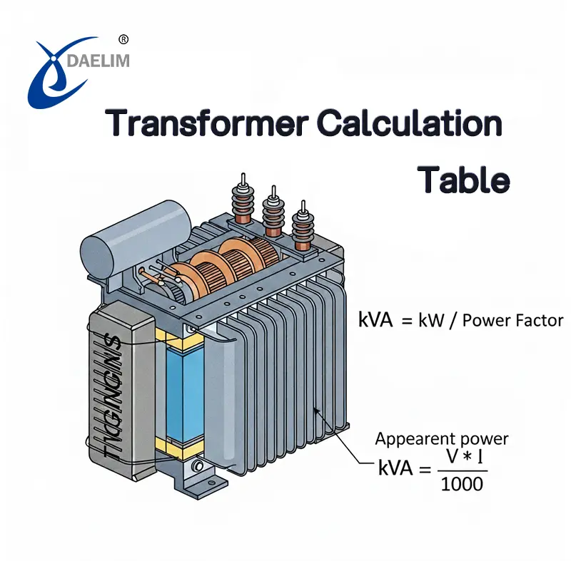
The power rating of any Electrical Transformer is simply the product of its electrical voltage and the current that passes through the Electrical Transformer winding. The power rating of the Electrical Transformer is represented in kilo volt ampere so to convert the normal voltage unit volts and current unit ampere into kilo volt ampere we need to divide the product of the electrical voltage and current by 1000. The Transformer power rating formula is presented below:

In the above formula, the KVA represents Electrical Transformer power rating, V represents the voltage in volts applied across Electrical Transformer and I represents electrical current in ampere that passes through the Electrical Transformer winding.
Transformer Power Rating (Three Phase)
 The Transformer power rating for 3 phase Electrical Transformer is almost same as that of the single phase Electrical Transformer with the only difference that the product of the Electrical Transformer voltage and the electrical current is also multiplied with the square root of 3. Similarly, to convert the volt ampere into kilo volt ampere, the product of electrical voltage and current is divided by 1000. Following is the formula to calculate the Transformer power rating for 3 phase Electrical Transformer.

Transformer Current Calculation
In the case you are not provided with the electrical current needed by the application or you have to calculate whether your existing Transformer has the capability to meet the current need of the specific application, then you can perform the Transformer current calculation to understand whether your given Transformer has the ability to deliver the required current or not.
To get the electrical current calculation, you will use the formula provided in the above Transformer power calculation section. The following is the modified shape of the transformer power rating calculation formula to calculate the current for any given Electrical Transformer.

Efficiency Calculation
In order to calculate the efficiency of the Electrical Transformer, you need to estimate the losses that occur in the Electrical Transformer that can include the core losses and the copper losses. After calculating all the losses, you can calculate the Transformer efficiency by dividing the power output that you get from your Electrical Transformer with power input that you provide to the Electrical Transformer. Following is the formula to calculate the Transformer electrical efficiency.

Impedance and Voltage Drop
You also need to calculate the Transformer impedance and voltage drop due to this impedance. The Transformer impedance is usually associated with the material quality as it is mainly the material electrical conductivity that will define the resistance faced by the electrical current when it flows through the Transformer winding.
So to calculate the Transformer voltage drop due to the impedance, you can use the following formula that is the product of electrical current with the Transformer impedance and electrical voltage being divided by 100. Following is the formula to calculate voltage drop in Electrical Transformer due to Transformer impedance.
In the above formula, Z represents the Electrical Transformer impedance that is usually associated with the material with which the Electrical Transformer winding and core is manufactured.

Transformer Sizing and Load Capacity Calculations
In the process of Electrical Transformer design, it is important to properly size the Electrical Transformer against the given load or you will be faced with the problem of lower power capacity than needed. Transformer sizing works in a way that it is based on the amount of kilo volt ampere needed to be delivered by the Transformer in order to satisfy a specific kilo watts of electrical load attached to the Transformer.
This Transformer sizing is done based on a factor called Electrical Transformer power factor and this Electrical Transformer power factor value depends on the application against which the Electrical Transformer is being designed. Following is the formula to calculate the Transformer kilo volt ampere against the electrical load kilowatts.

As we have explained, the power factor depends on the application, so we will go through three sample calculations to show how the power factor defines the kilo volt ampere of the transformer.
Residential Load Example
First, we take the residential load example where we will calculate the Transformer kilo volt ampere needed to satisfy an electrical load of 10 kilowatt. Now the power factor for the residential load is always considered to be around 0.9. So putting the values in the above formula will give you the 10/0.9 = 11.11 kVA.
So to safely provide a residential load of 10 kilo Watts, an Electrical Transformer with power rating of 11.11 kilo volt ampere is needed.
Industrial Machine
If we perform a similar calculation for industrial machinery like for any manufacturing plant or any other industrial unit, then we have to consider a different power factor as manufacturing plants really have higher load requirements and due to which their power factor is usually around 0.85. So if we put 10 kilowatt of electrical load with the power factor of 0.85, we get a Transformer power rating of 11.76 kVA.
To safely deliver 10 kilowatt of electrical load to any industrial unit, you need an Electrical Transformer with the power rating of 11.76 kilo volt ampere which is about 0.65 kilo volt ampere more than that of the residential load.
Data Center
Do a similar set of calculations with consideration that the Transformer will be delivered for a data centre, then we have a load factor of 0.95. This is because the data centre usually has a sensitive piece of equipment that draws a fixed amount of electrical load and doesn't show much variation. So to deliver an electrical load of 10 kilo Watts to a data centre, we need an Electrical Transformer with the power rating of 10.57 kilowatt ampere.
You may enjoy: Transformers Solution For Data Center and blockchain
Single Phase Transformer Sizing Table
During the Transformers sizing process you need to predict the wire size required based upon the Transformer kilo word ampere rating the voltage applied and the full load current that process in this electrical circuit.
Following is a complete table for Transformers sizing of wire.

| kVA Rating | Voltage (V) | Full Load Amps | Wire Size | Typical Applications |
| 5 | 240 | 20.83 | #10 AWG | Small shops, lighting |
| 15 | 240 | 62.5 | #4 AWG | Homes, small offices |
| 25 | 240 | 104.2 | #2 AWG | HVAC, welding shops |
Three Phase Transformer Amperage Chart
| kVA | Voltage (Line to Line) | Full Load Amps | Cable Size | Use Case |
| 30 | 480 | 36.1 | #8 AWG | Light industrial equipment |
| 75 | 480 | 90.2 | #3 AWG | Motor loads, manufacturing |
| 150 | 480 | 180.4 | 1/0 AWG | Data centers, large motors |
Transformer Calculation Table
| Calculation Type | Formula | Variables | Sample Calculation |
| Single Phase kVA Rating | kVA = (V × I) / 1000 | V = 240 V, I = 50 A | kVA = (240 × 50) / 1000 = 12 kVA |
| Three Phase kVA Rating | kVA = (√3 × V × I) / 1000 | V = 415 V, I = 100 A | kVA = (1.732 × 415 × 100) / 1000 = 71.87 kVA |
| Transformer Current | I = (kVA × 1000) / V | kVA = 75, V = 480 V | I = (75 × 1000) / 480 = 156.25 A |
| Efficiency (%) | η = (Output Power / Input Power) × 100 | Output = 95 kW, Input = 100 kW | η = (95 / 100) × 100 = 95% |
| Voltage Drop | V_drop = I × Z × V / 100 | I = 100 A, Z = 5%, V = 400 V | V_drop = 100 × 5 × 400 / 100 = 20 V |
| Load in kVA (from kW) | kVA = kW / Power Factor | kW = 20, PF = 0.8 | kVA = 20 / 0.8 = 25 kVA |
| Line to Neutral Voltage | V_Ph = V_L / √3 | V_L = 415 V | V_Ph = 415 / 1.732 = 239.5 V |
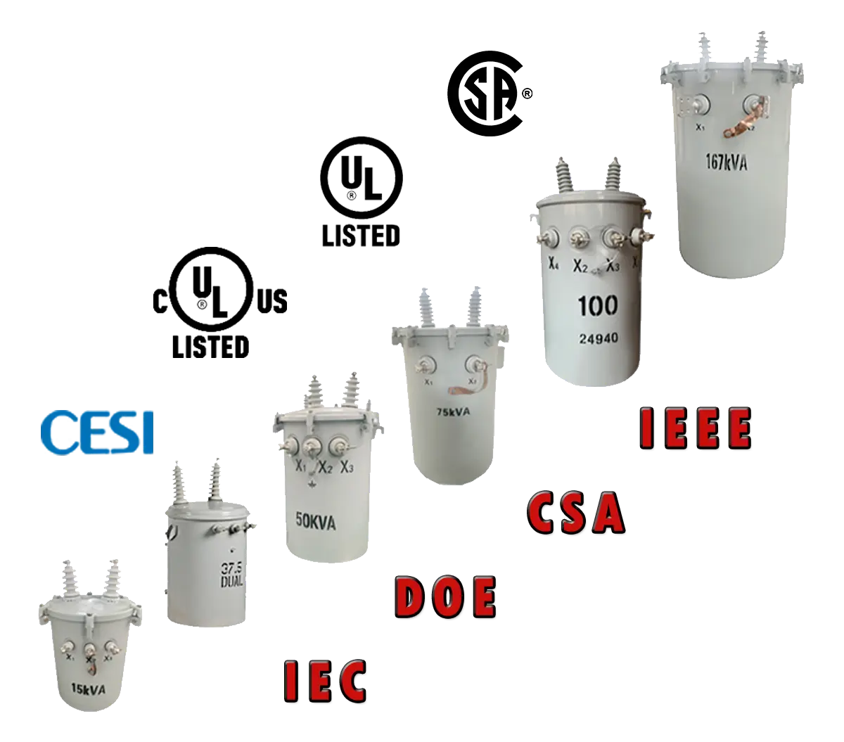
Reference List of Transformer Rating in kVA
| kVA Rating | Application Type | Typical Use Cases |
| 10 | Residential | Lighting, basic appliances |
| 50 | Commercial | Shops, small offices |
| 150 | Industrial | Medium sized motors |
| 500 | Utility/Distribution | Substations, heavy machinery |
| 1000–5000 | High capacity Industrial | Power plants, large facilities |
Design Considerations and Safety Margins
 To be on the safe side, it is very important to have the following design considerations and always include safety margins when you are doing Electrical Transformer design calculation.
- Always consider a factor of safety when designing an Electrical Transformer for any given electrical load. It is important to have a 20 to 30% margin above the calculated electrical load to ensure that the Transformer designed for the given application will not fail under peak electrical load.
- It is possible to have heat or extreme environmental conditions during its useful life, so it is important to consider high ambient temperature and other factors during the designing of the Electrical Transformer in order to avoid Electrical Transformer failure on hot summer days due to excessive heat.
- It is also important to consider the location of your Electrical Transformer installation because your Transformer might be installed at a very elevated height where thinner air might affect the cooling and insulation performance of your Electrical Transformer.
- It is the duty of the Electrical Transformer designer to consider any potential further growth plan if not provided by the client. This will help you and your customer to have a Transformer that will not fail in the near future.
Conclusion
As Electrical Transformers are sensitive electrical devices, they need proper design calculations during the designing stage to deliver safe and reliable electricity in any type of application. We have provided a brief guide on transformer design calculations, along with a sample calculation table to help you determine accurate transformer sizing easily.
Follow Up

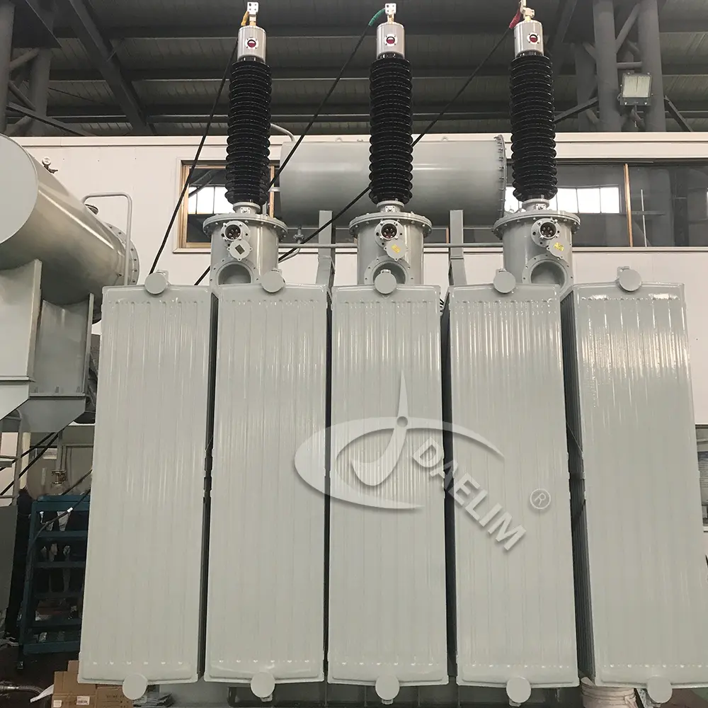
At Daelim Transformer, we design and develop electrical Transformers of all types, sizes and different power capacities. Our team of expert electrical engineers has over ten years of experience in performing all types of transformer design calculations and delivering transformers that meet every customer’s requirements. If you have any questions about transformer design or calculations, our team is ready to assist you in any way possible.
Related Products

Related Article
How Transformers and PDUs Work Together for Data Center Power
In data centers, uninterrupted power is crucial. Transformers step down high-voltage grid power to usable levels, while PDUs distribute it to IT infrastructure. Together, they maintain continuous, efficient power flow, preventing costly disruptions even during brief outages.
How much electricity is lost in Transmission
When electricity is transmitted from a utility to consumers, some energy is inevitably lost, making it a costly aspect of modern power systems. These losses occur during transmission and distribution, affecting both energy efficiency and operating costs. Annually, about 5–8% of generated electricity is lost, highlighting the need for improved infrastructure and energy management strategies.
Transformer Overcurrent Protection
A transformer is vital in power distribution and industry but vulnerable to overcurrent faults from overloads, short circuits, or system issues. Such conditions can damage components, shorten lifespan, and cause financial losses. Hence, overcurrent protection is not optional but essential to ensure reliability, safety, and cost efficiency in transformer operations.
Top 5 Mistakes to Avoid When Choosing Transformers for Blockchain
Reliable electricity is essential for blockchain. A key factor in every successful mining farm is the right transformer. Whether for small setups or large-scale industrial blockchain operations, choosing an efficient, dependable transformer ensures stable power, maximizes performance, prevents costly downtime, and supports the growing energy demands of blockchain infrastructure.
Beginner Guide To Iron Core Transformer
Iron core transformers are widely used due to their efficient magnetic flux transfer between primary and secondary windings. Their performance depends on core design and material quality. Made from iron, these cores offer superior magnetic properties. This article covers types, manufacturing processes, advantages, disadvantages, and applications, highlighting why iron cores outperform other materials in transformer construction.
How Much is a Transformer
Electrical transformers are essential for safe, reliable electricity in residential, industrial, and utility systems. Buyers must understand pricing, which depends on transformer type, application, and specifications. Proper budgeting requires knowing cost-driving factors, including design, capacity, and usage requirements, to ensure the right transformer is purchased for specific industrial, utility, or infrastructure needs.