Understanding Transformer Impedance: Balancing Resistance and Reactance for Optimal Performance
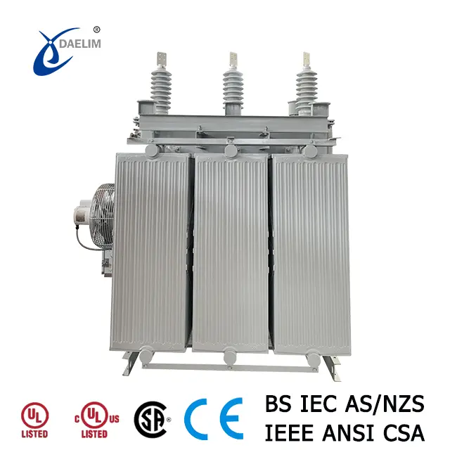
Transformer impedance is a pivotal parameter in design, combining resistance and reactance that impede alternating current within the system. Expressed as a percentage, it is crucial for determining the safe current-carrying capacity of a transformer without risking overheating. The impedance value must be precisely balanced; it should neither be excessively high nor too low to ensure efficient operation and prevent damage. For high-voltage (HV) power transformers with larger capacities, the impedance typically ranges around 10%.
Contact Daelim TransformerWhat is Transformer Impedance?
Transformer impedance encompasses resistance and reactance, which oppose the flow of alternating current. It is represented as a percentage of the voltage required to drive the transformer to full load. The impedance value typically increases with the transformer’s capacity. For distribution transformers, the impedance usually falls within 4%.

Role of Impedance in Transformers
Impedance plays several key roles in transformer operation:
- Short Circuit Protection: It limits the maximum fault current during short circuits.
- Voltage Regulation: Helps manage voltage differences across the transformer.
- System Efficiency: Influences the voltage drop across windings and the core’s maximum flux density.
Transformer Efficiency: The Ultimate FAQs Guide
Calculating Transformer Impedance
Impedance can be calculated using a short circuit test. The formula is:
Z%=(Short Circuit Voltage×100)/Rated Voltage
For instance, with a short circuit voltage of 104V and a rated voltage of 4160V:
Z%=(104×100)/4160=2.5%
You may enjoy: The primary guide of delta star transformer
Typical Impedance Values
The typical impedance values of transformers vary according to different standards. The following lists the transformer impedance values of IEEE, CSA, and AS standards.
According to IEEE C57.12.34 standards
- 45 - 75 kVA: 2.7%-5.75%
- 112.5 - 300 kVA: 3.1%-5.75%
- 500 kVA: 4.35%-5.75%
- 750-2500kVA: 5.75%
- 3750kVA: 5.75%-6%
- 5000-10000kVA: 6%-6.5%
Reading more about IEEE C57 Standard
According to CSA C227.4 standards
Minimum transformer impedance
- 0 - 150 kVA: 1.8%
- 225 - 300 kVA: 2%
- 500kVA: 3%
- 750 - 1000 kVA: 4%
- 1500 - 3000 kVA: 5%
Reading more about CSA C227.4
According to AS/NZS 60076.5 standards
- 25 - 630 kVA: 4%
- 631 - 1,250 kVA: 5%
- 1,251 - 2,500 kVA: 6%
Larger transformers generally have higher impedance to accommodate their increased capacity.
Read more: The ultimate guide to ONAN transformers
High vs. Low Impedance
- High Impedance: Provides better protection against short circuits and poor power factors but can lead to increased voltage drops and overheating.
- Low Impedance: Minimizes voltage regulation and is typically more efficient but may result in higher short circuit currents and additional costs due to the need for more robust equipment.
Get it now: How to buy an electric pole transformer?
Factors Affecting Transformer Impedance
Transformer impedance is influenced by:
- Number of Turns: More turns increase impedance.
- Core Material: Ferrite cores generally have higher impedance.
- Core Size and Winding Resistance: Larger cores and different winding arrangements affect impedance.
Measuring Transformer Impedance
A short circuit test is commonly used:
- Setup: Apply a voltage to the HV windings while keeping the LV windings short-circuited.
- Measure: Record the voltage and current to determine impedance.
Try for free: Solar Transformer - Your ultimate guide
Modifying Transformer Impedance
Impedance can be adjusted by changing the number of winding turns or altering core size and material. Increasing turns raises impedance while decreasing turns lowers it.
Conclusion
Transformer impedance is essential for safe and efficient transformer operation. It affects short circuit protection, voltage regulation, and system efficiency. Understanding and correctly managing impedance is crucial for optimizing transformer performance.
Daelim Transformer, with over 20 years of expertise, can design transformers with optimal impedance values, ensuring high efficiency and stability. Contact Daelim Transformer to meet your specific impedance needs.
Related Products
Related Article
13.8 kV 10.5 MVA Substation Transformer for Ecuador
A customer from Ecuador contacted Daelim Transformer for a 10.5MVA substation transformer (13.8kV high voltage, 2.4kV low voltage). Daelim Transformer provided a customized solution, conducted virtual factory tours, ensured rigorous quality control via video inspections, and offered post-delivery online training and ongoing support, fostering a successful partnership.
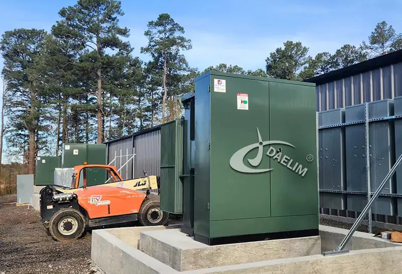
2600 kVA Pad Mounted Transformer for Blcokchain
Daelim Transformer successfully provided three customized 2600 kVA pad mounted transformers to power a state-of-the-art blockchain facility in Texas, USA. Our transformers were meticulously designed to meet the unique demands of the mining operation, ensuring seamless power distribution with unwavering reliability and efficiency.
20MVA Power Transformer for the United States
This project involves the development of a 20 MVA three-phase power transformer tailored for the United States market. The primary voltage is 24.94kV, and the secondary voltage is 4.16kV, indicating it functions as a step-down transformer. The design and production fully comply with IEEE C57.12.00 standards and have passed third-party UL team testing. All accessories also adhere to IEEE standards. FR3 vegetable oil serves as the insulating liquid for the transformers.
1500 kVA Transformer for Australian Mining Project
Introduce the 1500 kVA transformer tailored for Australian mining projects. The transformer operates in a three-phase configuration, with a total of four units deployed. Notably, its primary voltage stands at 11kV, while the secondary voltage is 1kV. Characterized by its compact size, emphasis on safety, and unwavering reliability, this transformer is meticulously designed and manufactured to meet the stringent requirements outlined in AS 60076 and AS efficiency value standards.Let's delve into the key features and specifications of this essential solution.
2 MVA Pad Mounted Transformer for Utility
Behold the backbone of Canada's utility infrastructure—the 2MVA pad mounted transformer. With a primary voltage of 4160Grdy/2400V and a secondary voltage of 800GrdY/461V, this transformer stands as a testament to efficiency and reliability in power distribution. Crafted in strict accordance with CSA standards and CAN/CSA802.1 energy efficiency guidelines, it embodies the pinnacle of engineering excellence.
2600 kVA Pad Mounted Transformer For Blockchain In Kansas
This morning, I received the on-site photos of the pad-mounted transformers from the customer, and I was overwhelmed with excitement and joy. These pad-mounted transformers are installed at a 20MW blockchain site in Kansas, USA. A total of 5 sets of 2600 kVA pad-mounted transformers, all UL-listed, are being deployed at this site. Currently, 3 sets have already been installed onsite and are scheduled to be powered on imminently.