How Do You Wire a Transformer | A Step by Step Guide
Electrical transformers are a combination of complex electrical connections and electrical wiring that help them to safely and reliably deliver the required electrical current and voltage to the electrical load attached. With this question of how do you wire a transformer so that it can deliver electricity safely and reliably.
This guide is all about understanding how you wire a Transformer. This will be a very detailed and comprehensive step by step guide on Electric Transformer wiring. We will deliver all basic concepts associated with the Electrical Transformer wiring and will deliver you comprehensive safety precautions that you need to consider before during and after the Electrical Transformer wiring process.
Contact Daelim TransformerKey Concepts in Transformer Wiring
What Does “Wiring a Transformer” Mean?
The term Electrical Transformer wiring for wiring a transformer is usually referred to a process in which the one end of Electrical Transformer is connected to the electricity generator source like any power plant over generator and its other end is connected to the electric load for which the electricity is being regulated by the Electrical Transformer.
Transformer input and Output
During the Transformer wiring the connections that came from the electricity generating source will be labelled as the input and in the Electrical Transformer that input is done on the primary transformer winding.
Similarly during the Transformer wiring the connections that provide electricity to the electrical load attached to the Electrical Transformer are labelled as the Transformer output and in electrical Transformers these outputs are always the secondary winding of the Electrical Transformer.
Single Phase and Three Phase Transformers Wiring
While doing the Electrical Transformer wiring it is very important to understand the nature of the Electrical Transformer and what type of electricity it will be providing. An Electrical Transformer that is designed and developed to deliver single phase electricity will be connected in a manner that it receives a one single phase of electricity and delivers electricity to a single phase electrical load.
Similarly the Electrical Transformer is designed and developed to handle three phase electricity where it will receive 3 different inputs for 3 different phases of electricity. The output of the three phase Electrical Transformer will also consist of three different wires that provide electricity to a three phase electrical load.
Terminal Markings and Color Codes
 To make things easy and convenient for communication between different departments of the same manufacturing facility between different manufacturing facilities. The terminals of the electrical Transformers on which different connections will be made are marked, labelled and colour coded.
Determiners at which the input of the Electrical Transformer will be attached or usually labelled as H1 and H2. These both terminals are primary winding terminals at which we will be receiving the input with livewire at one and that at the other.
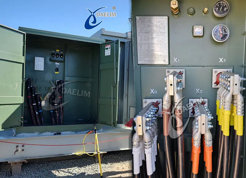
Similarly the terminals at which the Electrical Transformer output will be available will be labelled X1 and X2. Both of these terminals will be at the secondary winding of the Electrical Transformer.
Depending on the regional laws and national standards the transformer manufacturing and assembling unit also does some specific colour codes to identify different spots and terminals of the Electrical Transformer during Transformer wiring.
If you have an Electrical Transformer with colour codes then you can refer to the manufacturer manual on which they will be at in this detailed description about the colour coding of each Electrical Transformer terminal.
Wiring Safety Precautions
Electrical transformers are huge and can weigh a few hundred kgs and any mishandling can result in serious accidents and injuries to the worker. There are some certain safety questions that you need to follow during the Electrical Transformer wiring for procedure.
- Before approaching the Electrical Transformer for making Electrical Transformer wiring, make sure that you have complete personal protective equipment like goggles, gloves and all of your tools are properly insulated to protect you from any type of electrical short circuit.
- Before you start making the electrical connection between the Electrical Transformer and the power generating source make sure that the power generating source is not generating electricity at the moment or the Electrical Transformer input wire or not connecting to any live electrical connection.
- Similarly connecting the wires for the Electrical Transformer output terminals make sure that the wire does not connect any electrical load that is in running condition.
- Before and during the Electrical Transformer wiring process make sure that you know the process by the book and I have the required wire diagram to show that all the electrical connections and wiring are made as per international standards especially compiling the national electrical codes and any other regional laws.
- During the wiring of electrical transfer make sure that you have all the necessary and proper tools to make an efficient and reliable electrical connection of Electrical Transformer. use of improper tools can be prevented, dangerous to the operator and the payment itself.
Step by Step Guide to Wiring a Transformer
Having a basic understanding of Transformer wiring and complete understanding of safety precautions related to the Transformer wiring procedure we will now discuss step by step procedure of how to hook up transformer for both single phase and three phase Electrical Transformers.
Single Phase Transformer Wiring
This single phase transformer wiring consists of several steps with each step dedicated to solving specific problems or performing specific tasks. The following is a detailed and step by step guide on single phase transformer wiring.
Identify Transformer Type
The first step in the Transformer wiring is the identification of the type of single phase Electrical Transformer. You need to know whether it is a step up Electrical Transformer or a step down Electrical Transformer. Similarly you need to know whether it is a dry type or a wet type Electrical Transformer because steps might have different updates based on the type of the Electrical Transformer.
Setup Before Wiring
As Electrical Transformers are wired after they are installed on the specific site, you need to consider the process of wiring the Electrical Transformer by keeping in mind that the Transformer has already been installed on the site and cannot move as you will.
Depending on the Electrical Transformer design, you might have terminals on the top of the Electrical Transformer for Electrical Transformer wiring or you can have input terminals on one side of the Electrical Transformer and output terminals on the other side of the transformer. There is also a chance of having all four electrical terminals on the same side of the transformer. So you need to plan your approach depending on the Electrical Transformer design and space available on the site of installation of the Electrical Transformer.
You need to make sure that the wire and the tools and you yourself can easily access the terminals without any object interfering with its ability to safely make a proper electrical connection.
You need to identify the input and output terminals that are universally labelled as H1, H2 and X1, X2.
Turn Off All Power
Before approaching the Electrical Transformer for the Transformer wiring, you need to make sure that all power coming in the lines is turned off and there is no live power in the wire that you are going to connect with the Electrical Transformer.
Wiring of Transformer
There is a specific sequence of wiring the single phase Electrical Transformer and you need to follow the sequence in order to ensure your safety and reliability of the electrical wiring.
- First step in the wiring of a single phase Electrical Transformer is the connection of the single phase wiring with the input of the Electrical Transformer that is with the terminal H1 and H2.
- The second step is the grounding of the Electrical Transformer that is done by connecting the Transformer with the grounding wire, which is usually labelled as G or GND and is connected to the Transformer grounding bar or to the bus bar in the electrical panel of the transformer.
- The third step is connecting the Electrical Transformer output terminals to the wires that lead to the electrical load. These wires are connected with the X1, X2 terminals of the Electrical Transformer.
It is important to consider and keep in mind the polarity of the single phase electrical wiring being done on the Electrical Transformer. Polarity is the direction of the voltage in the Transformer winding and you need to consider it especially when you are making a parallel operation.
To have a better understanding of the Electrical Transformer wiring, we will look at two very common Electrical Transformer wiring examples.
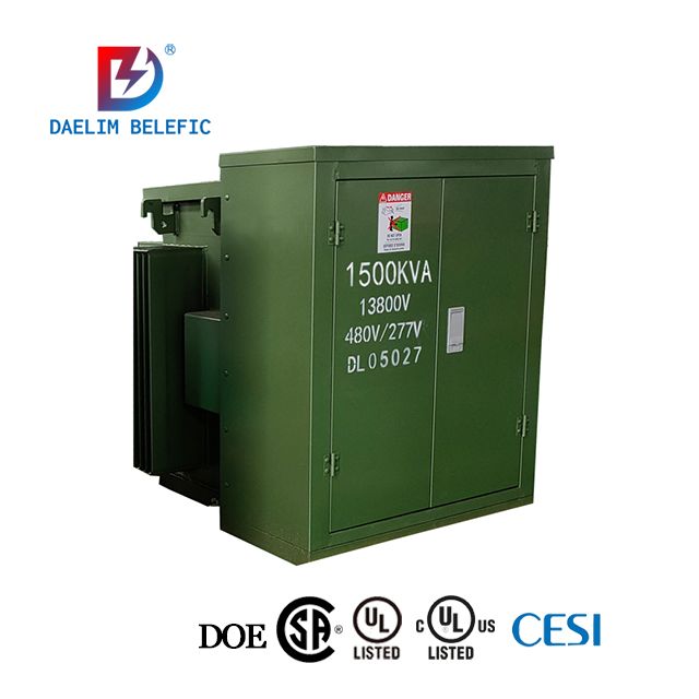
How to Wire a Transformer 480V to 120V
- First, identify the input terminals of the Electrical Transformer that will be labeled as H1 and H2.
- Now take the two wires that are coming from the electric power generating plant that generates 480 volts.
- Connect one wire with the H1 terminal and the other wire with the H2 terminal. The Transformer input wiring is now complete.
- Now connect the Electrical Transformer output with the electrical load of 120V. Take the two wires that will be leading towards the electrical load and connect them with the output terminals of the Electrical Transformer that will be labelled as X1 and X2.
- Connect one wire with the X1 and the other wire with the X2, keeping in mind the polarity of the electrical connection initially made at the Transformer input.
- Now you have completed the Electrical Transformer Wiring from 480V to 120V. Electrical Transformer will step down from 480 volts to 120 volts.
How to Wire a Transformer 480V to 240V
- First, identify the input terminals of the Electrical Transformer that will be labeled as H1 and H2.
- Now take the two wires that are coming from the electric power generating plant that generates 480 volts.
- Connect one wire with the H1 terminal and the other wire with the H2 terminal. The Transformer input wiring is now complete.
- Now connect the Electrical Transformer output with the electrical load of 240V. Take the two wires that will be leading towards the electrical load and connect them with the output terminals of the Electrical Transformer that will be labelled as X1 and X2.
- Connect one wire with the X1 and the other wire with the X2, keeping in mind the polarity of the electrical connection initially made at the Transformer input.
Now you have completed the Electrical Transformer Wiring from 480V to 240V. Electrical Transformer will step down from 480 volts to 240 volts.
Three Phase Transformer Wiring
 Three phase electrical transformer wiring can be done in two different configurations. One is called Delta configuration and the other is called Star configuration. The way in which the three phases of the electrical connection are provided to the transformer is different for both configurations. We will discuss both configurations in detail here and will explain how wiring for each configuration is done.
Wiring of Transformer in Delta Configuration
In Delta configuration, there is no neutral wire in the wiring of the Electrical Transformer. In the Delta configuration, the line voltage is the phase voltage of the Electrical Transformer and these types of electrical transformers are commonly used in high power 3 phase applications like industrial motors and for large machinery.
The following are the common steps that you need to follow for wiring a transformer in Delta configuration.
- In three phase Electrical Transformer wiring, we have two ends for each phase of the electric voltage, that is, for 3 windings we have 6 terminals in total.
- We have H1 and H2 for phase A, H3 and H4 for phase B and H5 and H6 for phase C on the primary side of the transformer that is at the high voltage side.
- At the secondary side, which is the low voltage side of the electrical transformer, we have X1 and X2 for phase A, X3 and X4 for phase B and X5 and X6 for phase C.
- For the wiring of the Electrical Transformer in Delta configuration, you need to connect the H2 with the H3 terminal, H4 with H5 terminal and you need to connect the H6 with H1 terminal.
- Now you need to connect line one with H1 terminal, line two with H3 terminal and line three with H5 terminal of the Electrical Transformer. Complete the Delta loop on the primary side of the Electrical Transformer.
- Now to do Electrical Transformer wiring in Delta configuration on the secondary side of the Electrical Transformer, you need to connect X2 with X3, X4 with X5 and connect X6 with X1 terminal of the Electrical Transformer.
- To get output three phase voltage from the Transformer, you need to connect phase A with X1 terminal, phase B with the X3 terminal and phase C with the X5 terminal. This will complete the Delta configuration loop on the secondary side of the transformer.
Note that there is no neutral wire setup in the Delta configuration for three phase Electrical Transformer. There are three wires and three phase output from this configuration wiring.
Wiring of Transformer in Star Configuration
In Star configuration of three phase Electrical Transformer one end of each of the three transformer windings is connected to the common point called the neutral point. The other ends of the windings are connected to the line conductors to form the complete Electrical Transformer winding.
The following are the important points and procedure to form a Star configuration 3 phase Electrical Transformer wiring.
- In Star configuration the primary side of the three phase Electrical Transformer has 6 terminals in total and they are labelled as H1, H2, H3, H4, H5 and H6. The combination of two terminals is used for one phase. Similarly in the secondary winding there are 6 terminals labelled as X1 and X2, X3 and X4, X5 and X6 two terminals for each winding of the three phase Electrical Transformer.
- To start the wiring process for Star configuration 3 phase Electrical Transformer, you need to connect one end of each of the windings together like you need to connect one end of H2, H4 and H6 together at one common point that gives them a shape of star. This common point will also be known as the neutral point.
- After that, you need to connect the remaining ends of all three windings to the incoming line supply. Like, you need to connect H1 with line one, H3 with line two and you need to connect H5 with line three.
- At the secondary winding section, you need to connect one end of each of the windings together. You need to connect X2 with X4 and with X6 and they will become the neutral point.
- After that, you need to connect the load lines with the other ends of the winding. You can connect phase A with terminal X1, phase B with terminal X3 and phase C with terminal X5.
The Star configuration helps you get single phase electricity from this three phase configuration of Electrical Transformer. For example, if you have 400 volts line to line system voltage, then the line to neutral voltage will be 400 / √3 that is 230 volts. So you get 400 volts between any two phases and you get 230 volts between any one phase and the neutral wire. So you can get both single phase electrical voltage and a three phase electrical voltage from the same three phase Electrical Transformer with Star configuration.
Conclusion

Electrical Transformers are really complex electrical devices and their proper wiring is very important to get safe and reliable electricity. We have comprehensive content on how to wire a transformer. We have delivered to you all the basic information about the Transformer wiring and detailed safety precautions that you need to follow during the Electrical Transformer installation. To deliver you better content, we have discussed in detail step by step electrical wiring of single phase Electrical Transformer and 3 phase Electrical Transformer. In single phase Electrical Transformer we have delivered to you sample calculations and sample wiring on how you can wire step down electrical transformers. In 3 phase Electrical Transformer wiring, we have delivered to you two different configurations that are done during the wiring of the Electrical Transformer.
Follow Up

Daelim Transformer manufacture Transformers of every type, size and different power capacity. Each and every Electrical Transformer that is designed and developed by our expert teams of engineers can satisfy all types of national and international standards of electrical performance and environmental safety.
If you have any questions related to Electrical Transformers you can contact us and our team of experts will help you solve your problem.
Related Products
Related Article
Transformer Overcurrent Protection
A transformer is vital in power distribution and industry but vulnerable to overcurrent faults from overloads, short circuits, or system issues. Such conditions can damage components, shorten lifespan, and cause financial losses. Hence, overcurrent protection is not optional but essential to ensure reliability, safety, and cost efficiency in transformer operations.
Top 5 Mistakes to Avoid When Choosing Transformers for Blockchain
Reliable electricity is essential for blockchain. A key factor in every successful mining farm is the right transformer. Whether for small setups or large-scale industrial blockchain operations, choosing an efficient, dependable transformer ensures stable power, maximizes performance, prevents costly downtime, and supports the growing energy demands of blockchain infrastructure.
Beginner Guide To Iron Core Transformer
Iron core transformers are widely used due to their efficient magnetic flux transfer between primary and secondary windings. Their performance depends on core design and material quality. Made from iron, these cores offer superior magnetic properties. This article covers types, manufacturing processes, advantages, disadvantages, and applications, highlighting why iron cores outperform other materials in transformer construction.
How Much is a Transformer
Electrical transformers are essential for safe, reliable electricity in residential, industrial, and utility systems. Buyers must understand pricing, which depends on transformer type, application, and specifications. Proper budgeting requires knowing cost-driving factors, including design, capacity, and usage requirements, to ensure the right transformer is purchased for specific industrial, utility, or infrastructure needs.
Transformer Calculation Table
Electric transformers are crucial for stepping voltage up or down in power distribution. Proper transformer calculations, considering consumer requirements and international design standards, are essential for accurate voltage regulation. Understanding transformer specifications, formulas, and sizing methods is key. The article provides examples and a calculation table to guide readers through the transformer design and selection process effectively.
Electrical Transformer Site Acceptance Testing
Site Acceptance Testing (SAT) is essential for electrical transformers to ensure safe, reliable performance after design, transport, and installation. Since transformers regulate power for sensitive equipment, any error can cause serious damage. SAT verifies proper functioning on-site through critical tests, preventing failures and ensuring compliance with operational and safety requirements.