
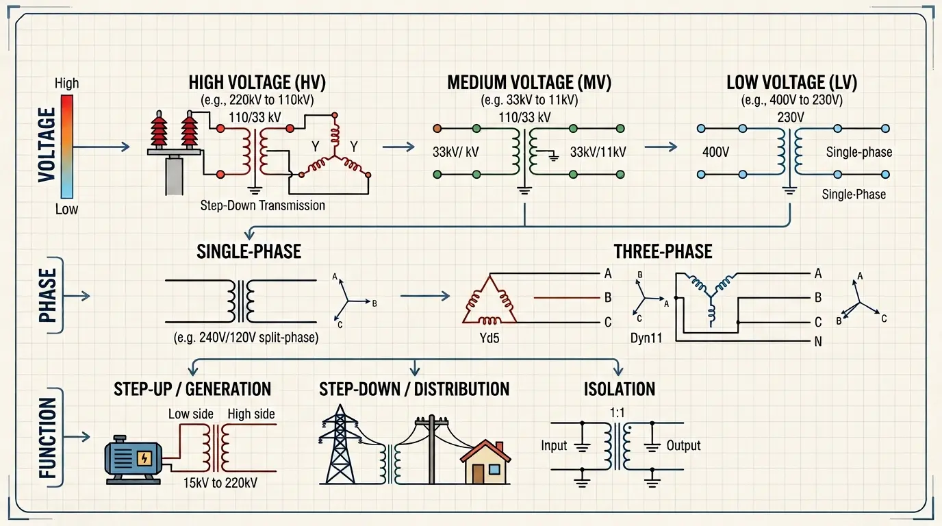
The transformer wiring diagram is an important parameter for engineers to accurately make connections and installations in different systems. Wiring diagrams of transformers are based on phase, voltage phases, and their practical operations. In this tutorial, we will make different transformer wiring examples for practical operations and accurate voltage regulation.
Transformer Wiring Diagrams based on Voltage
Above 2.4kV Class Transformer Wiring Diagram
In this transformer wiring diagram, the primary winding is connected to a medium-voltage supply of more than 2.4 kV (such as 4.16 kV, 12.47 kV, 13.8 kV, 24.94 kV, or 34.5 kV), depending on the utility or industrial system. Its secondary voltages are three-phase 480 V, 400 V, 600 V, 690 V, or 277 V, according to load.
This transformer wiring comes with high voltage protection devices like surge arrestors and load break switches and breakers on the primary side that manage overload as well as short circuits.
These wiring connections are employed in renewable energy plants, heavy industries, and data centers where a medium-voltage step-down transformer is needed.
These transformers also separate the medium voltage grid and the low voltage industrial system. Secondary voltage provides safe operation and is used for motors and lighting system switchboards.
For handling faults of circuits, proper grounding of the transformer tank and neutral is applied.
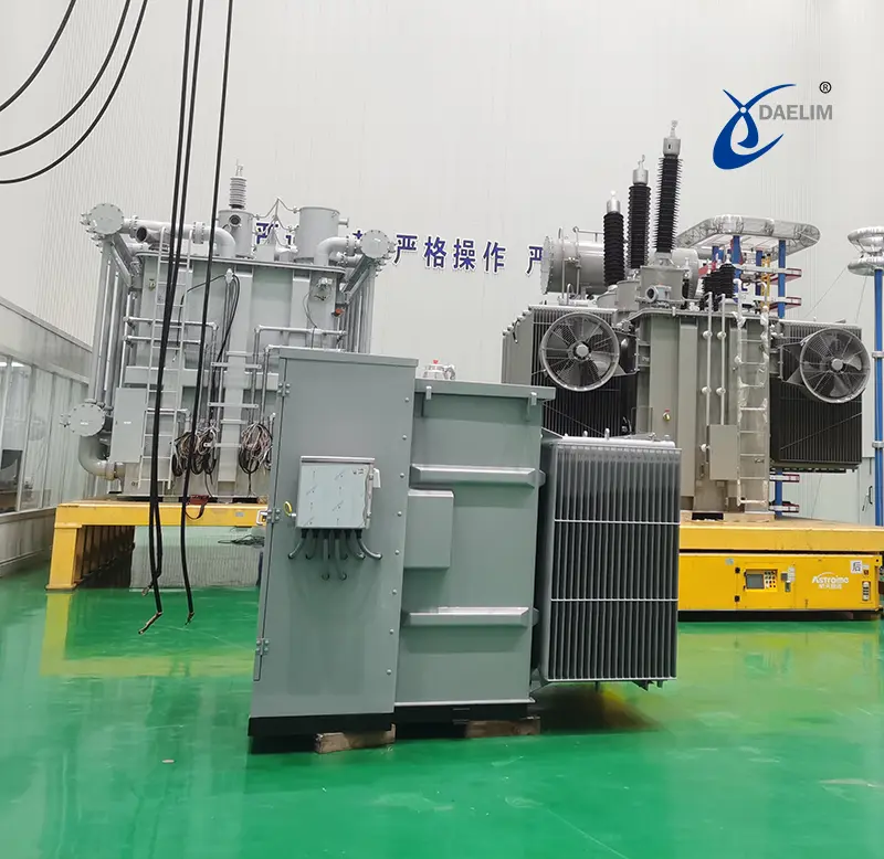
In this transformer wiring diagram, the primary winding is connected to a medium-voltage supply of more than 2.4 kV (such as 4.16 kV, 12.47 kV, 13.8 kV, 24.94 kV, or 34.5 kV), depending on the utility or industrial system. Its secondary voltages are three-phase 480 V, 400 V, 600 V, 690 V, or 277 V, according to load.
This transformer wiring comes with high voltage protection devices like surge arrestors and load break switches and breakers on the primary side that manage overload as well as short circuits.
These wiring connections are employed in renewable energy plants, heavy industries, and data centers where a medium-voltage step-down transformer is needed.
These transformers also separate the medium voltage grid and the low voltage industrial system. Secondary voltage provides safe operation and is used for motors and lighting system switchboards.
For handling faults of circuits, proper grounding of the transformer tank and neutral is applied.
Medium-Voltage to 480V / 400V / 600V Step-Down Transformer
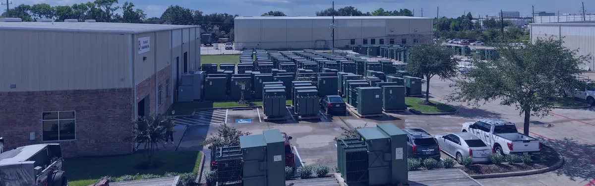
In this transformer wiring configuration, the primary side comes with a medium voltage input of more than 2.4 kV, and a protection circuit breaker is employed.
Its secondary side outputs are
- 480 V three-phase
- 400 V three-phase
- 600 V three-phase
- 690 V three-phase
- or other required industrial voltage levels
These transformers are part of industrial motors, pumping systems, HVAC chillers, and also commercial buildings that use three-phase voltage. For these wiring connections, an accurate vector group and identification of phase are needed for accurate system support and safe function.
Read our guide: Advantages of Transformer Yyn0 Vector Group
This transformer minimizes medium voltage supply into a standard low voltage level for industries and is also effective for large-scale power distribution.
120/240V or 240/480V Single-Phase Output Transformer
These single phase transformers for different applications offer single-phase low-voltage output, like 120/240 V or 240/480 V, with a center-tapped secondary winding. The primary side has medium voltage more than 2.4 kV configured with H1-H2-H3 (3-phase primary systems).
Its center tap operates like a neutral that provides
- 120 V line-to-neutral
- 240 V line-to-line
- or 240/480 V configurations
These transformer categories are employed for commercial applications and utility distribution systems, where single-phase supply is used from a medium-voltage system.
Medium-Voltage to Industrial Low-Voltage (277V – 690V)
These transformers’ primary sides come with medium voltage input more than 2.4 kV and come with a protection circuit breaker, and in some applications, switchgear is used.
Its secondary side output comes with
- 480 V three-phase
- 400 V three-phase
- 600 V three-phase
- 690 V three-phase
These transformers are part of manufacturing lines, pumping systems, HVAC chillers, and industrial motors that need three-phase voltage.
In these wiring connections, important factors are accurate vector group and phase identification to provide safe functioning.
Medium-Voltage Buck-Boost / Voltage Adjustment Transformer
- Buck-boost transformers perform minor voltage correction with standard industrial levels like 480 V, 600 V, or 400 V in a medium voltage distribution system compared to small control voltages.
- These transformers are connected in series to the load for setting voltage in the required tolerance limits. They are employed in industries where long cables cause voltage losses. It was also employed in devices where voltage regulation was needed.
600V Transformer Wiring Diagram
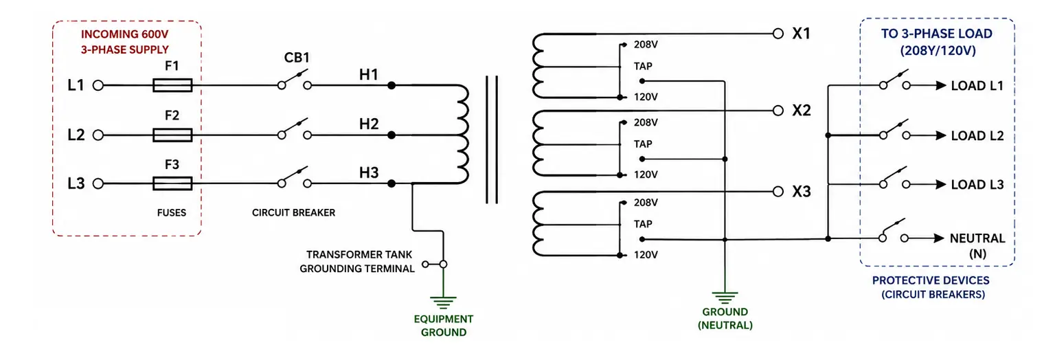
Primary connected with a 600V input whose terminals are labeled with markings H1, H2, and H3 for the phases. The secondary side provides a lower voltage or 3-phase output.
It also comes with grounding, protective devices, and different taps for flexible operations.
These transformers are part of a heavy industrial high-voltage system, a larger-scale power distribution.
high-voltage transformer made for the following electrical code or safety standards.
There is a need for protection devices for the transformer and connected devices.
Transformer Wiring Diagrams by Phase
Single-Phase Transformer Wiring
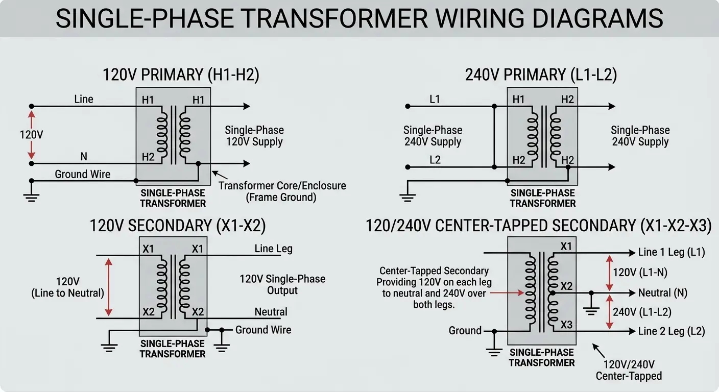
Single-phase transformers are part of residential homes, offices, and commercial lighting in commercial buildings. Their supply voltage range is 120 V or 240 V.
A single-phase system comes with line, neutral, or ground conductors. For a 120V system, the live wire is connected with H1, the neutral with H2, and the ground with the transformer core/enclosure. In a 240V system, L1 is connected with H1, and L2 is connected with H2.
The secondary side provides 120V line to neutral or 240V line to line, according to design.
For residential applications, a system center-tapped secondary provides 120V on each leg to neutral and 240V over both legs.
Three-Phase Transformer Wiring
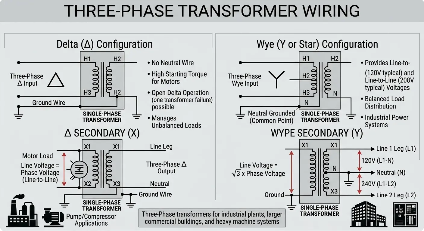
three phase transformer part of industrial plants, larger commercial buildings, and heavy machine systems. They offer smooth power with high efficiency. It comes in two configurations
Delta (Δ) Configuration
This configuration comes in windings configured end to end for making a closed loop like a triangle. It does not come with a neutral wire.
It comes with line voltage the same as phase voltage and is employed for motor loads and manages unbalanced loads compared to the wye
Its main features are provide high strength starting motor, it continuously operate in open delta, either single transformer not working
It is used in pumps, compressors and heavy devices
Wye (Star) Configuration
This design comes with one end winding connected to the neutral or common point. Its neutral is grounded.
Its main features are a line voltage equal to √3 × phase voltage. It provides line-to-neutral and line-to-line voltages. It offers balanced load distribution.
Wiring Diagrams by Function
Step-Down Transformer Wiring
- A step-down transformer is used to minimize the high input voltage to a level that is applicable. Common examples are 480V to 120V, 240V to 24V, and 277V to 120V. It is a commonly used transformer in an electrical power system.
- The wiring configuration of this transformer comes with a primary side that is high voltage, comes with a connected power source that has a circuit breaker, and also has a disconnect switch and a grounded enclosure.
- The secondary side comes with a lower voltage given to the load and also comes with a center tap for neutral. neutral connected with ground
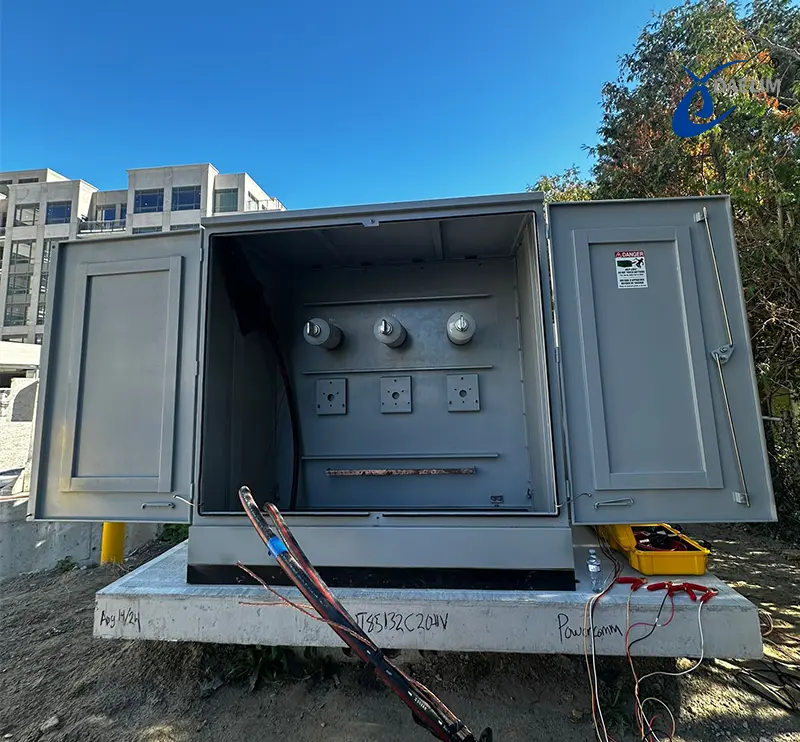
Buck-Boost Transformer Wiring
A buck-boost transformer is employed for performing voltage corrections. It performs voltage boosts or increases, and bucks voltage or reduces.
Its voltage adjustments are 208V to 230V, 240V to 208V, and 220V to 230V. It is not used for larger voltage transformation.
The wiring configuration of this transformer has the secondary winding connected with the power supply in a series combination. Voltage added or subtracted from the line.
It also comes with polarity, making x1 and x2. Its wiring comes with jumpers between primary and secondary. series connected with the load
If wiring connections are not accurate, it causes voltage to be canceled rather than boosted, overboost, and damage devices, resulting in overheating.
Buck-boost transformers are used for correcting voltage losses for longer cable lines. It makes an industrial device voltage correction.
Isolation Transformer Wiring
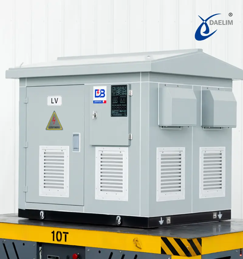
Isolation transformers offer galvanic partitions between input and output circuits. It does not have electrical continuity between primary and secondary. In this energy transfer, through the phenomenon of magnetic induction.
Isolation protects from shock, reduces noise, and decreases the ground loop surge protection buffer.
Isolation transformer wiring comes with separate primary and secondary windings that do not have electrical connections between circuits. It also has independent grounding paths.
The isolation transformer secondary is floating, not connected to the ground, and used for providing high isolation.
These windings can be grounded, come with one side connected to the ground, and are used where a system needs a stable reference voltage.
Isolation transformers offer galvanic partitions between input and output circuits. It does not have electrical continuity between primary and secondary. In this energy transfer, through the phenomenon of magnetic induction.
Isolation protects from shock, reduces noise, and decreases the ground loop surge protection buffer.
Isolation transformer wiring comes with separate primary and secondary windings that do not have electrical connections between circuits. It also has independent grounding paths.
The isolation transformer secondary is floating, not connected to the ground, and used for providing high isolation.
These windings can be grounded, come with one side connected to the ground, and are used where a system needs a stable reference voltage.
Transformer Wiring Symbols & Schematics
Understanding of wiring symbols is important for converting schematic diagrams into practical ones
Common Transformer Symbols
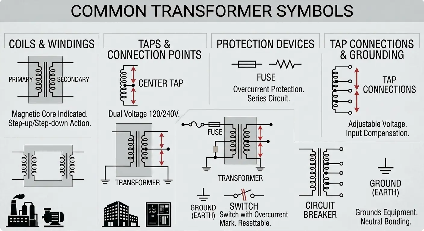
Coils (Windings)
Coils or windings are in curved loops. Two sets are for primary and secondary windings. Parallel vertical lines exist between coils, showing the magnetic core.
Center Tap
It is shown for the connection point for the center of the winding. employed for making neutral, make dual voltage 120/240V
Ground Symbol
It is in 3 descending horizontal lines. Shoes protect the earth, ground the equipment, and provide a neutral bonding point.
Fuse Symbol
Small rectangles or zigzags in series combinations that come with overcurrent protection and are used on primary windings.
Circuit Breaker
It is a switch symbol having an interruption marking, which offers resettable overcurrent protection.
Tap Connections
These are branch point windings employed for setting output voltage and compensating for supply changes.
Read our guide: How Do You Wire a Transformer | A Step by Step Guide
Conclusion
Transformer wiring diagrams are important references used by technicians and engineers for safe and accurate installations. An accurate understanding and explanation of wiring diagrams are helpful for voltage level verification, phase connections, grounding, polarity, and protection devices that are important for controlling faults and maintaining accurate transformer functions.
Accurate wiring techniques compatible with stable voltage regulation, overload protection, and compliance with installation codes and electrical standards.
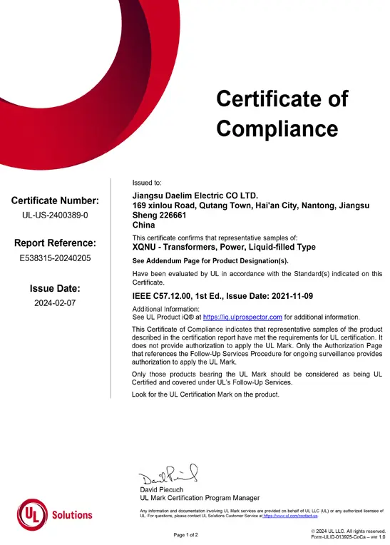
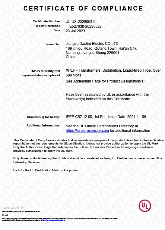

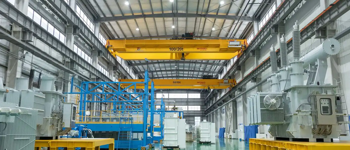
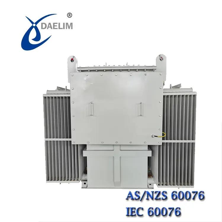
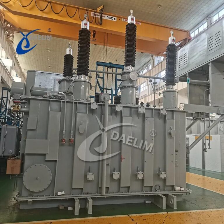
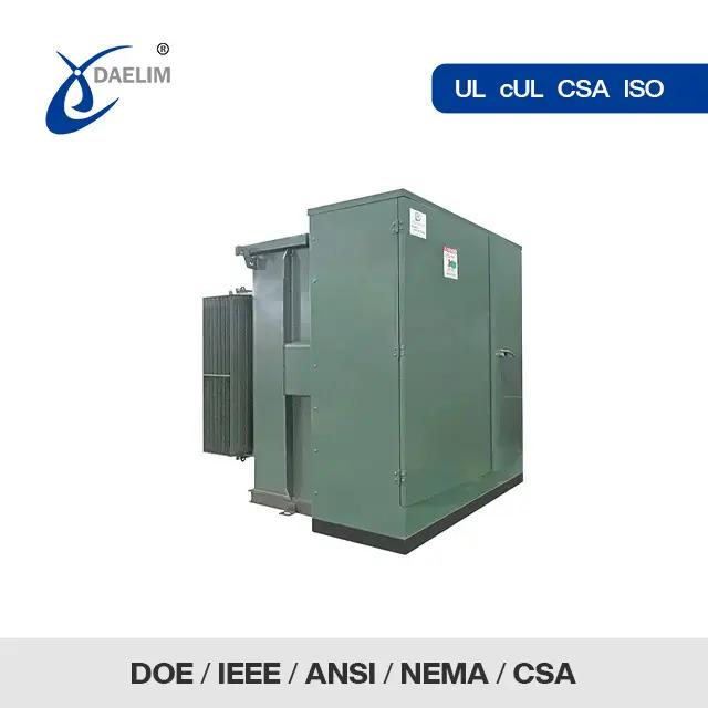
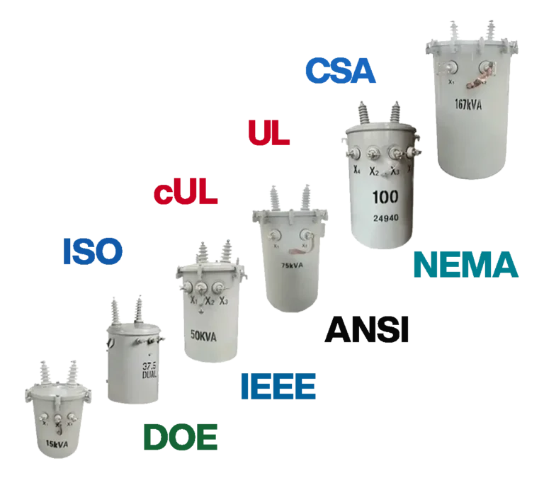
For engineers and project planners, Daelim Transformer offers different rating transformers for fulfilling required international standards such as IEEE, UL, and IEC. They also offer customized transformer designs and technical support for fulfilling different system demands.
FAQs
How to read a wiring diagram for a transformer?
A common symbol is two wavy lines that are coil-shaped and denote transformer windings. With that, some small circles or letters show different terminals, like P used for primary windings and S for secondary windings.
How to check the transformer primary and secondary?
The easy method is to check the nameplate connected with the winding. Manufacturers connected the nameplate of the input or primary winding and the secondary with the secondary windings of the transformer.
What are L1, L2, and L3 wiring?
For electrical wiring, L1, L2, and L2, L3 show 3 separate live wires with a 3-phase power system having 120 degrees out of sync with each other, offering constant power for larger motors and industrial devices. L shows Line, and L1, L2, and L3 show different phases.

 English
 Polish
 German